Mobile Router
Overview
This chapter discusses the menus that you can use to monitor the Nebula-managed Mobile Routers in your network and configure settings even before a Mobile Router is deployed and added to the site.
A Nebula Mobile Router is an LTE or NR cellular 5G indoor or outdoor router that can be managed by Nebula. It is referred to as a Nebula Device in this chapter. To identify whether your Nebula Device is an outdoor or indoor device and view the list of the Nebula Devices that can be managed through the NCC, go to Help > Support tools > Device function table.
Configuration
From the navigation panel, click Mobile router and the following screen appears. The Mobile router > Configuration screen allows you to view the information of your indoor or outdoor Nebula Device in a selected site. To edit the Name, MAC address, Serial number, Description, Address, and Tags of your Nebula Device, click the edit icon ( ) in the Configuration field.
) in the Configuration field.Mobile Router > Configuration (Indoor)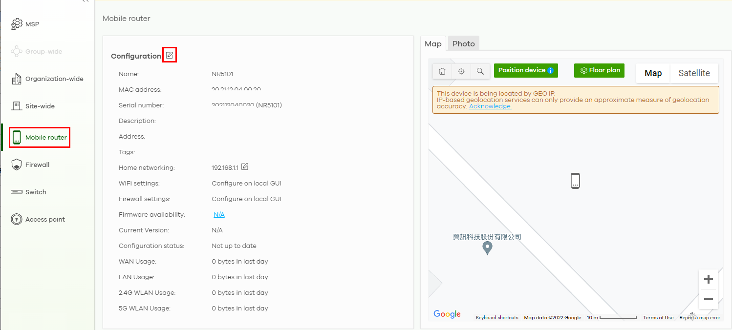
Mobile Router > Configuration (Outdoor)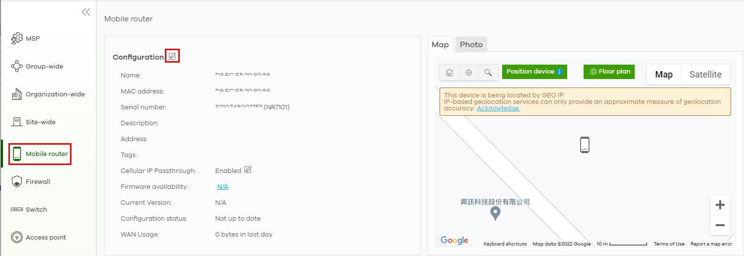
Configuration: Edit
The following screen displays after you click the edit icon. Use the Mobile router > Configuration: Edit screen to configure your indoor and outdoor Nebula Device information. You can also move the Nebula Device to another site.
Mobile Router > Configuration: Edit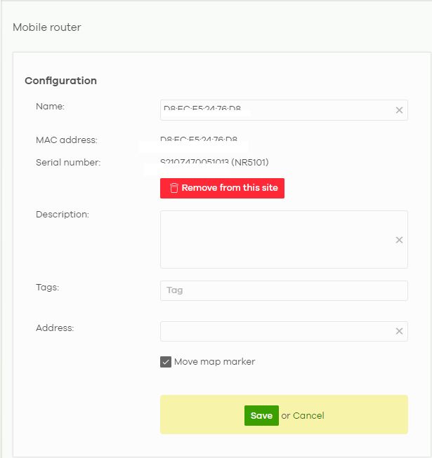
The following table describes the labels in this screen.
Label | Description |
|---|---|
Configuration | |
Name | Enter a descriptive name for the Nebula Device. |
MAC address | This shows the MAC address of the Nebula Device. |
Serial number | This shows the serial number of the Nebula Device. |
Description | Enter a user-specified description for the Nebula Device. |
Tags | Enter a user-specified tag for the Nebula Device. |
Address | Enter a user-specified address for the Nebula Device. |
Save | Click Save to save your changes. |
Cancel | Click Cancel to exit this screen without saving. |
Home Networking
To configure the Home networking setting, click the edit icon ( ) in the Home networking field.
) in the Home networking field.Mobile Router > Configuration: Home networking (Indoor)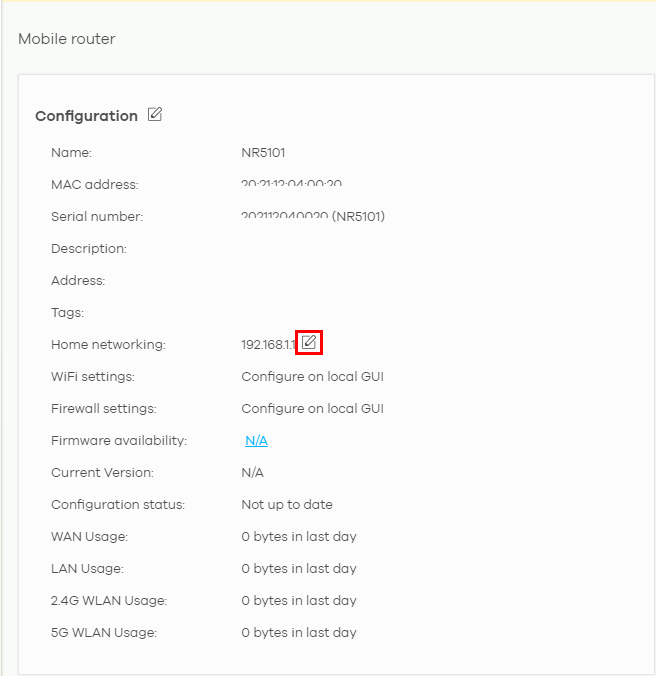
The following Mobile router > Configuration > Home networking: Edit screen displays. Use this screen to configure the LAN IP address and DHCP server settings of your indoor Nebula Device.
Mobile Router > Configuration > Home networking: Edit
The following table describes the labels in this screen.
Label | Description |
|---|---|
IP address assignment | |
IP address | Enter the IP address for this interface. |
Subnet mask | Enter the subnet mask of this interface in dot decimal notation. The subnet mask indicates what part of the IP address is the same for all computers in the network. |
DHCP setting | |
DHCP Server | Select this to disable or enable the DHCP server. |
IP pool start address | Enter the IP address from which the Nebula Device begins allocating IP addresses. |
Pool size | Enter the number of IP addresses to allocate. This number must be at least one and is limited by the interface’s Subnet mask. For example, if the Subnet mask is 255.255.255.0 and IP pool start address is 10.10.10.10, the security gateway can allocate 10.10.10.10 to 10.10.10.254, or 245 IP addresses. |
Lease time | Specify how long each computer can use the information (especially the IP address) before it has to request the information again. Choices are: Infinite – select this if IP addresses never expire; days, hours, minutes – select this to enter how long IP addresses are valid. |
Close | Click Close to exit this screen without saving. |
OK | Click OK to save your changes. |
Cellular IP Passthrough
To configure the cellular IP passthrough setting, click the edit icon ( ) in the Cellular IP Passthrough field. IP passthrough allows a LAN computer on the local network of the Nebula Device to have access to web services using a public IPv4 address. When IP passthrough is configured, all traffic is forwarded to the LAN computer and will not go through NAT.
) in the Cellular IP Passthrough field. IP passthrough allows a LAN computer on the local network of the Nebula Device to have access to web services using a public IPv4 address. When IP passthrough is configured, all traffic is forwarded to the LAN computer and will not go through NAT.Mobile Router > Configuration: Cellular IP Passthrough (Outdoor)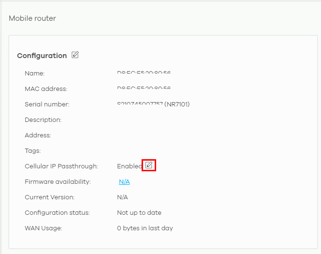
The following Mobile router > Configuration > Cellular IP Passthrough: Edit screen displays. Use this screen to disable or enable IP passthrough on your outdoor Nebula Device. Slide the switch to the right to enable IP passthrough.
Mobile Router > Configuration > Cellular IP Passthrough: Edit
The following table describes the labels in this screen.
Label | Description |
|---|---|
IP Passthrough mode | This displays if IP passthrough is enabled on the Nebula Device. |
Close | Click Close to exit this screen without saving. |
OK | Click OK to save your changes. |
Firmware Status
Go back to the Mobile router > Configuration screen to view the firmware version and WAN/LAN/WLAN usage of your indoor or outdoor Nebula Device.
Mobile Router > Configuration > Firmware status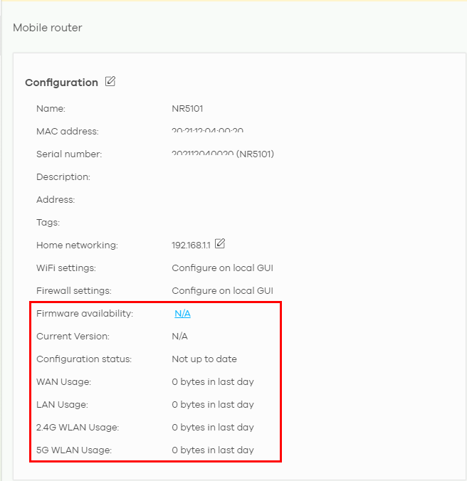
The following table describes the labels in this screen.
Label | Description |
|---|---|
WiFi settings | Configure the Nebula Device’s WiFi settings using its Web Configurator. Refer to the Nebula Device’s User’s Guide for more information. |
Firewall settings | Configure the Nebula Device’s firewall settings using its Web Configurator. Refer to the Nebula Device’s User’s Guide for more information. |
Firmware availability | The NCC automatically detects whether the firmware is up-to-date or not. Click the value in the Firmware availability field to go to the Site-wide > Configure > Firmware management screen and configure your Firmware management settings. |
Current Version | This shows the firmware version currently installed on the Nebula Device. |
Configuration status | This shows whether the configuration on the Nebula Device is up-to-date. |
WAN Usage | This shows the total amount of data consumed by the Nebula Device on the WAN (uplink/downlink) in the past 24 hours. |
LAN Usage (indoor NCCs only) | This shows the total amount of data consumed by the Nebula Device on the LAN (upllink/downlink) in the past 24 hours. |
2.4G WLAN Usage (indoor NCCs only) | This shows the total amount of data consumed by the Nebula Device on the 2.4G WiFi network (uplink/downlink) in the past 24 hours. |
5G WLAN Usage (indoor NCCs only) | This shows the total amount of data consumed by the Nebula Device on the 5G WiFi network (uplink/downlink) in the past 24 hours. |
Map/Photo
Click the Map tab. This shows the location of the Nebula Device on Google map. To upload a photo of the Nebula Device, select the Photo tab.
Mobile Router > Map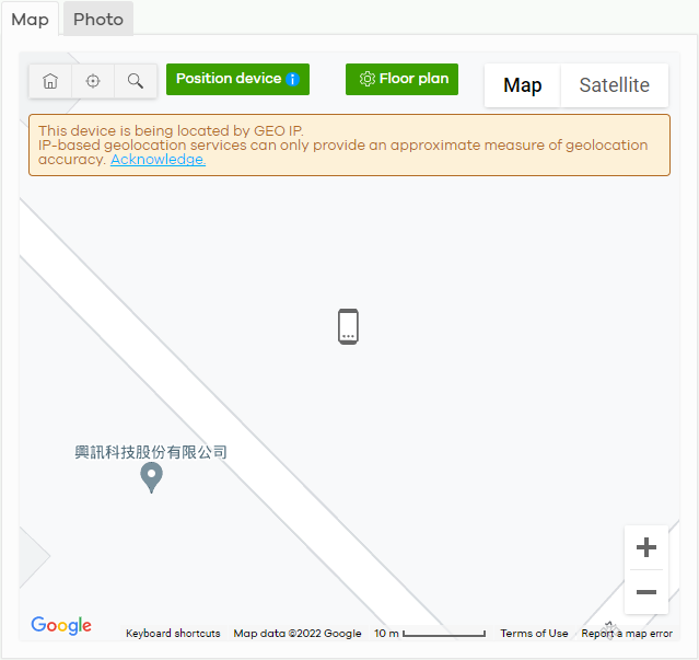
The following table describes the labels in this screen.
Label | Description |
|---|---|
Map | This shows the location of the Nebula Device on Google Maps (Map view or Satellite imagery view) or on a floor plan. Click Floor plan to display a list of existing floor plans. Each floor plan has a drawing that shows the rooms scaled and viewed from above. Drag-and-drop your Nebula Device directly on the Google map or click Position device to update the Nebula Device’s address (physical location). • Select GEO IP to use the public IP address of the Nebula Device. • Select Get my location from web browser to use the public IP address of the computer accessing the NCC portal. • Select Use the following address or coordinates to enter the complete address or coordinates of the Nebula Device. |
Photo | This shows the photo of the Nebula Device. Click Add to upload up to five photos of your Nebula Device. Click the remove icon (  ) to delete a photo. ) to delete a photo. |
Live Tools
Use live tools to view various interface information, system/security logs, perform diagnostics, reboot or establish a remote connection to the Nebula Device.
Mobile Router > Live tools > Traffic (Example)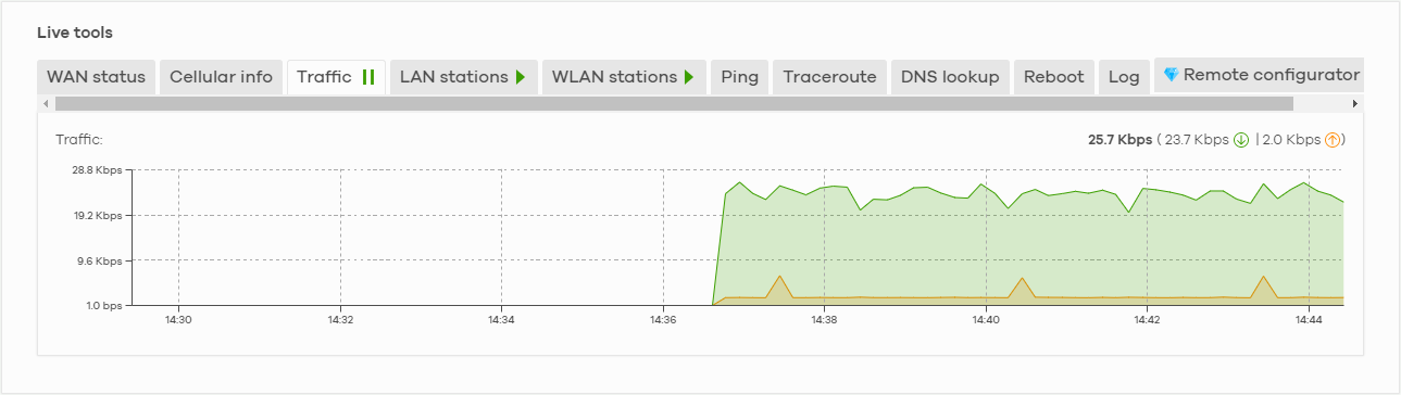
 ) to stop getting data for the respective screens. Alternatively, click the play icon (
  ) to continue.
The following table describes the labels in this screen.
Label | Description |
|---|---|
WAN Status | This shows the connection status of the Ethernet WAN interface. See WAN Status for more information. |
Cellular info | This shows the connection status of the cellular WAN interface. See Cellular Info for more information. |
Traffic | This shows the Nebula Device traffic statistics. The y-axis represents the transmission rate for uplink and downlink traffic. The x-axis represents the time period over which the traffic flow occurred. |
LAN stations | This shows the Nebula Device’s connected LAN clients’ MAC address and IPv4 Address. |
WLAN stations (indoor NCCs only) | This shows the Nebula Device’s connected WiFi clients’ MAC address, SSID name, IPv4 address, Signal strength, Security, Channel, Tx rate, Rx rate, Tx/Rx, and Capability. See WLAN Stations for more information. |
Ping | Enter the hostname or IP address of a computer that you want to perform ping from the Nebula Device in order to test a connection and click Ping. This can be used to determine if the Nebula Device and the computer are able to communicate with each other. |
Traceroute | Enter the domain name or IP address of a computer that you want to perform traceroute from the Nebula Device and click Run. This determines the path a packet takes to the specified computer. |
DNS lookup | Enter a host domain name and click Run to resolve the IP address for the specified domain name. |
Reboot | Click this button to restart the Nebula Device. |
Log | Select this to display System log and Security log entries in the past 24 hours. |
Remote configurator | Click Establish to use TCP (Transmission Control Protocol) port 443 to establish a remote connection to this Nebula Device. The Nebula Device will create a reverse SSH (Secure SHell) connection. After clicking Ok, NCC will provide a remote connection IPv4 address and service port number. For example, https://63.35.218.205:31479. Use this IPv4 address and port to connect to the Nebula Device to open the Web Configurator. The remote session will be available for 30 minutes. In case the connection cannot be established, confirm that the network allows Port 443. |
WAN Status
Go to the Mobile router > Live tools > WAN status screen to view the Ethernet WAN status of the Nebula Device.
Mobile Router > Live tools > WAN status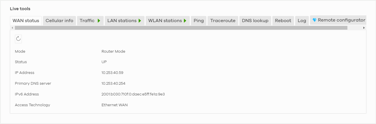
The following table describes the labels in this screen.
Label | Description |
|---|---|
 | Click this button to reload the data-related frames on this page. |
Mode | This displays which operating mode the Nebula Device is assigned to. |
Status | This displays whether the Nebula Device is online/offline. |
IP Address | This shows the LAN IPv4 address of the Nebula Device. |
Primary DNS server | The shows the first DNS server address assigned by the ISP. |
IPv6 Address | This shows the LAN IPv6 address of the Nebula Device. |
Access Technology | This displays the type of the network (such as NR, LTE, Ethernet WAN) to which the Nebula Device is connecting. |
Signal Strength | This show the signal strength of the Nebula Device. |
Cellular Info
Go to the Mobile router > Live tools > Cellular Info screen to view the cellular WAN status of the Nebula Device.
Mobile Router > Live tools > Cellular Info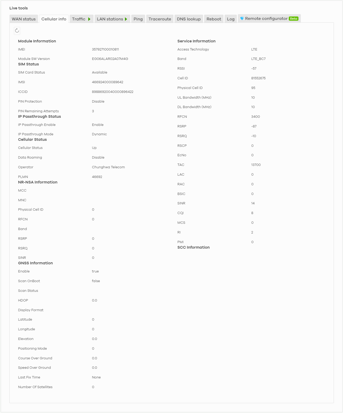
The following table describes the labels in this screen.
Label | Description |
|---|---|
Module Information | |
IMEI | This shows the International Mobile Equipment Identity of the Nebula Device. |
Module SW Version | This shows the software version of the cellular network module. |
SIM Status | |
SM Card Status | This displays the SIM card status: None – the Nebula Device does not detect that there is a SIM card inserted. Available – the SIM card could either have or does not have PIN code security. Locked – the SIM card has PIN code security, but you did not enter the PIN code yet. Blocked – you entered an incorrect PIN code too many times, so the SIM card has been locked. Call the ISP (Internet Service Provider) for a PUK (Pin Unlock Key) to unlock the SIM card. Error – the Nebula Device detected that the SIM card has errors. |
IMSI | This displays the International Mobile Subscriber Identity (IMSI) of the installed SIM card. An IMSI is a unique ID used to identify a mobile subscriber in a mobile network. |
ICCID | Integrated Circuit Card Identifier (ICCID). This is the serial number of the SIM card. |
PIN Protection | A PIN (Personal Identification Number) code is a key to a SIM card. This field shows Enable if PIN Protection is enabled. Otherwise, this field shows Disable. |
PIN Remaining Attempts | This is how many more times you can try to enter the PIN code before the ISP blocks your SIM card. |
IP Passthrough Status | |
IP Passthrough Enable | This displays if IP passthrough is enabled on the Nebula Device. IP passthrough allows a LAN computer on the local network of the Nebula Device to have access to web services using the public IP address. When IP passthrough is configured, all traffic is forwarded to the LAN computer and will not go through NAT. |
IP Passthrough Mode | This displays the IP passthrough mode. This displays Dynamic and the Nebula Device will allow traffic to be forwarded to the first LAN computer requesting an IP address from the Nebula Device. This displays Fixed and the Nebula Device will allow traffic to be forwarded to a specific LAN computer on the local network of the Nebula Device. |
Cellular Status | |
Cellular Status | This displays the status of the cellular Internet connection. |
Data Roaming | This displays if data roaming is enabled on the Nebula Device. 4G roaming is to use your NCC in an area which is not covered by your service provider. Enable roaming to ensure that your Nebula Device is kept connected to the Internet when you are traveling outside the geographical coverage area of the network to which you are registered. |
Operator | This displays the name of the service provider. |
PLMN | This displays the PLMN (Public Land Mobile Network) number. |
NR-NSA Information | This displays the status of the cellular Internet connection. |
MCC | This shows the Mobile Country Code (MCC). MCC is a unique code that identifies the country where a Public Land Mobile Network (PLMN) is at. |
MNC | This shows the Mobile Network Code (MNC). MNC is a unique code that identifies a Public Land Mobile Network (PLMN) in a country. MCC and MNC combined together are used to identify a globally unique PLMN. |
Physical Cell ID | This shows the Physical Cell ID (PCI), which are queries and replies between the Nebula Device and the mobile network it is connecting to. The normal range is 1 to 504. |
RFCN | This displays the Radio Frequency Channel Number of DL carrier frequency used by the mobile network to which the Nebula Device is connecting. The value depends on the type of the mobile network (such as LTE, UMTS, GSM) to which the Nebula Device is connecting: • For UMTS (3G), it is the UARFCN (UTRA Absolute Radio-Frequency Channel Number) as specified in 3GPP-TS.25.101. • For LTE/5G, it is the EARFCN (E-UTRA Absolute Radio-Frequency Channel Number) as specified in 3GPP-TS.36.101. The value is ‘0’ (zero) or ‘N/A’ if there is no network connection. |
Band | This displays the current cellular band of your Nebula Device. |
RSRP | This displays the Reference Signal Receive Power (RSRP), which is the average received power of all Resource Element (RE) that carry cell-specific Reference Signals (RS) within the specified bandwidth. The received RSRP level of the connected E-UTRA cell, in dBm, is as specified in 3GPP-TS.36.214. The reporting range is specified in 3GPP-TS.36.133. An undetectable signal is indicated by the lower limit, example –140 dBm. This parameter is for LTE only. The normal range is –30 to –140. The value is –140 if the Current Access Technology is not LTE. The value is ‘N/A’ if there is no network connection. |
RSRQ | This displays the Reference Signal Receive Quality (RSRQ), which is the ratio of RSRP to the E-UTRA carrier RSSI and indicates the quality of the received reference signal. The received RSRQ level of the connected E-UTRA cell, in 0.1 dB, is as specified in 3GPP-TS.36.214. An undetectable signal is indicated by the lower limit, example –240. This parameter is for LTE only. The normal range is –30 to –240. The value is –240 if the Current Access Technology is not LTE. The value is ‘N/A’ if there is no network connection. |
SINR | This displays the Signal to Interference plus Noise Ratio (SINR) of the SCC. |
Service Information | If the cellular service provider supports carrier aggregation (CA), then this section displays statistics for the connection’s primary component carrier (PCC). |
Access Technology | This displays the type of the network (such as NR, LTE, Ethernet WAN) to which the Nebula Device is connecting. |
Band | This displays the current cellular band of your Nebula Device. |
RSSI | This displays the cellular signal strength between an associated cellular station and the Nebula Device for this SCC. |
Cell ID | This shows the cell ID, which is a unique number used to identify the Base Transceiver Station to which the Nebula Device is connecting. The value depends on the Current Access Technology: • For GPRS, it is the Cell Identity as specified in 3GPP-TS.25.331. • For UMTS, it is the Cell Identity as defined in SIB3 3GPP-TS.25.331, 3GPP-TS.24.008. • For LTE/5G, it is the 28-bit binary number Cell Identity as specified in SIB1 in 3GPP-TS.36.331. The value is ‘0’ (zero) or ‘N/A’ if there is no network connection. |
Physical Cell ID | This displays the Physical Cell ID (PCI) of the SCC. |
UL Bandwidth (MHz) | This shows the uplink cellular channel bandwidth from the Nebula Device to the base station. According to 3GPP specifications, the bandwidths defined by the standard are 1.4, 3, 5, 10, 15, and 20 MHz. The wider the bandwidth the higher the throughput. |
DL Bandwidth (MHz) | This shows the downlink cellular channel bandwidth from the base station to the Nebula Device. According to 3GPP specifications, the bandwidths defined by the standard are 1.4, 3, 5, 10, 15, and 20 MHz. The wider the bandwidth the higher the throughput. |
RFCN | This displays the Radio Frequency Channel Number of DL carrier frequency used by the mobile network to which the Nebula Device is connecting. The value depends on the type of the mobile network (such as LTE, UMTS, GSM) to which the Nebula Device is connecting: • For UMTS (3G), it is the UARFCN (UTRA Absolute Radio-Frequency Channel Number) as specified in 3GPP-TS.25.101. • For LTE/5G, it is the EARFCN (E-UTRA Absolute Radio-Frequency Channel Number) as specified in 3GPP-TS.36.101. The value is ‘0’ (zero) or ‘N/A’ if there is no network connection. |
RSRP | This displays the Reference Signal Receive Power (RSRP), which is the average received power of all Resource Element (RE) that carry cell-specific Reference Signals (RS) within the specified bandwidth. The received RSRP level of the connected E-UTRA cell, in dBm, is as specified in 3GPP-TS.36.214. The reporting range is specified in 3GPP-TS.36.133. An undetectable signal is indicated by the lower limit, example –140 dBm. This parameter is for LTE only. The normal range is –30 to –140. The value is –140 if the Current Access Technology is not LTE. The value is ‘N/A’ if there is no network connection. |
RSRQ | This displays the Reference Signal Receive Quality (RSRQ), which is the ratio of RSRP to the E-UTRA carrier RSSI and indicates the quality of the received reference signal. The received RSRQ level of the connected E-UTRA cell, in 0.1 dB, is as specified in 3GPP-TS.36.214. An undetectable signal is indicated by the lower limit, example –240. This parameter is for LTE only. The normal range is –30 to –240. The value is –240 if the Current Access Technology is not LTE. The value is ‘N/A’ if there is no network connection. |
RSCP | This displays the Received Signal Code Power, which measures the power of channel used by the Nebula Device. The received signal level, in dBm, is of the CPICH channel (Ref. 3GPP TS 25.133). An undetectable signal is indicated by the lower limit, example –120 dBm. This parameter is for UMTS only. The normal range is –30 to –120. The value is –120 if the Current Access Technology is not UMTS. The value is ‘N/A’ if there is no network connection. |
EcNo | This displays the ratio (in dB) of the received energy per chip and the interference level. The measured EcNo is in 0.1 dB and is received in the downlink pilot channel. An undetectable signal is indicated by the lower limit, example –240 dB. This parameter is for UMTS only. The normal range is –30 to –240. The value is –240 if the Current Access Technology is not UMTS or there is no network connection. |
TAC | This displays the Tracking Area Code (TAC), which is used to identify the country of a mobile subscriber. The physical cell ID of the connected E-UTRAN cell, is as specified in 3GPP-TS.36.101. This parameter is for LTE only. The value is ‘0’ (zero) or ‘N/A’ if the Current Access Technology is not LTE or there is no network connection. |
LAC | This displays the 2-octet Location Area Code (LAC), which is used to identify a location area within a PLMN. The LAC of the connected cell is as defined in SIB 1 [3GPP-TS.25.331]. The concatenation of PLMN ID (MCC+MNC) and LAC uniquely identifies the LAI (Location Area ID) [3GPP-TS.23.003]. This parameter is for UMTS or GPRS. The value is ‘0’ (zero) if the Current Access Technology is not UMTS or GPRS. The value is ‘N/A’ if there is no network connection. |
RAC | This displays the RAC (Routing Area Code), which is used in mobile network “packet domain service” (PS) to identify a routing area within a location area. In a mobile network, the Nebula Device uses LAC (Location Area Code) to identify the geographical location for the old 3G voice only service, and uses RAC to identify the location of data service like HSDPA or LTE. The RAC of the connected UTRAN cell is as defined in SIB 1 [3GPP-TS.25.331]. The concatenation of PLMN ID (MCC+MNC), LAC, and RAC uniquely identifies the RAI (Routing Area ID) [3GPPTS. 23.003]. This parameter is for UMTS or GPRS. The value is ‘0’ (zero) if the Current Access Technology is not UMTS or GPRS. The value is ‘N/A’ if there is no network connection. |
BSIC | The Base Station Identity Code (BSIC), which is a code used in GSM to uniquely identify a base station. This parameter is for GPRS only. The value is ‘0’ (zero) if the Current Access Technology is not GPRS. The value is ‘N/A’ if there is no network connection. |
SINR | This displays the Signal to Interference plus Noise Ratio (SINR) in dB. This is also a measure of signal quality and used by the UE (User Equipment) to calculate the Channel Quality Indicator (CQI) that it reports to the network. A negative value means more noise than signal. |
CQI | This displays the Channel Quality Indicator (CQI). It is an indicator carrying the information on how good or bad the communication channel quality is. |
MCS | MCS stands for modulation coding scheme. The base station selects MCS based on current radio conditions. The higher the MCS the more bits can be transmitted per time unit. |
RI | This displays the Rank Indication, one of the control information that a UE will report to eNodeB (Evolved Node-B) on either PUCCH (Physical Uplink Control Channel) or PUSCH (Physical Uplink Shared Channel) based on uplink scheduling. |
PMI | This displays the Precoding Matrix Indicator (PMI). PMI is for transmission modes 4 (closed loop spatial multiplexing), 5 (multi-user MIMO), and 6 (closed loop spatial multiplexing using a single layer). PMI determines how cellular data are encoded for the antennas to improve downlink rate. |
SCC Information | If the cellular service provider supports carrier aggregation (CA), then this section displays statistics for the connection’s secondary component carriers (SCCs). |
GNSS Information | Global Navigation Satellite System (GNSS) sends position and timing data from high orbit artificial satellites. It works with GPS navigational satellites to provide better receiver accuracy and reliability than just using GPS alone. This is necessary for 5G networks that require very accurate timing for time and frequency synchronization. With GNSS, your can easily locate the Nebula Device with accurate information. |
Enable | This shows if GNSS is enabled. |
Scan OnBoot | This shows Enable if Scan OnBoot is enabled, so that GNSS runs automatically after the Nebula Device is turned on. |
Scan Status | This shows GNSS error codes for debugging by a qualified service technician. |
HDOP | Horizontal Dilution of Precision (HDOP) shows how accurate data collected by the Nebula Device is according to the current satellite configuration. A smaller value of HDOP means a higher precision. |
Display Format | This shows the latitude and longitude display modes. There are three modes: 0, 1, and 2. Below are examples for these modes shown in latitude/longitude. 0 – ddmm.mmmmN/S, dddmm.mmmmE/W 1 – ddmm.mmmmmm, N/S, dddmm.mmmmmm, E/W 2 – (–)dd.ddddd, (–)ddd.ddddd N/S/E/W: North/South/East/West “–” : Negative values refer to South latitude/West longitude respectively. Positive values refer to North latitude/East longitude respectively. |
Latitude | This shows the latitude coordinate of the Nebula Device. These positioning values (latitude, longitude, and altitude) help you locate the Nebula Device accurately. |
Longtitude | This shows the longitude coordinate of the Nebula Device. |
Elevation | This shows the altitude of the Nebula Device above sea level in meters. |
Positioning Mode | This shows the GNSS positioning mode. 2D (“2”) GNSS positioning mode displays latitude and longitude coordinates; 3D (“2”) GNSS positioning mode displays latitude and longitude coordinates, and elevation. |
Course Over Ground | This shows the course of the Nebula Device based on true North. Course Over Ground (COG) is different from the direction an object is headed, but the path derived from its actual motion (considered as Track), since the motion of an object is often with respect to other factors like wind and tides. |
Speed Over Ground | This shows the Speed Over Ground (SOG) of the Nebula Device. SOG is the true object speed over the surface of the Earth. |
Last Fix Time | This shows the last time in UTC format that the position of the Nebula Device was updated. |
Number of Satellites | This shows the number of current active satellites. GNSS requires at least four satellites to determine the position of the Nebula Device. |
LAN Stations
Go to the Mobile router > Live tools > LAN stations screen to view the LAN status of the Nebula Device. Click the pause icon ( ) to stop scanning for LAN stations. Alternatively, click the play icon (
 ) to continue scanning.
) to stop scanning for LAN stations. Alternatively, click the play icon () to continue scanning.Mobile Router > Live tools > LAN stations
The following table describes the labels in this screen.
Label | Description |
|---|---|
MAC address | This field displays the MAC address of the LAN station. |
IPv4 address | This indicate the IPv4 address of the LAN station. |
WLAN Stations
Go to the Mobile router > Live tools > WLAN stations screen to view the WiFi status of the Nebula Device. Click the pause icon ( ) to stop scanning for WiFi stations. Alternatively, click the play icon (
 ) to continue scanning.
) to stop scanning for WiFi stations. Alternatively, click the play icon () to continue scanning.Mobile Router > Live tools > WLAN stations
The following table describes the labels in this screen.
Label | Description |
|---|---|
MAC address | This field displays the MAC address of an associated WiFi station. |
SSID name | This is the descriptive name used to identify the Nebula Device in a WiFi network. |
IPv4 address | This indicate the IPv4 address of the gateway that helps forward this route’s traffic. |
Capability | This shows the WiFi standard supported by the client or the supported standards currently used by the client. |
Security | This displays the type of security mode the WiFi interface is using in the WiFi network. |
Channel | This is the channel number currently used by the WiFi interface. |
Tx rate | This shows the maximum transmission rate of the client. |
Tx | This shows the amount of data transmitted by the client since it last connected. |
Rx rate | This shows the maximum reception rate of the client. |
Rx | This shows the amount of data received by the client since it last connected. |
Signal strength | This shows the RSSI (Received Signal Strength Indicator) of the client’s WiFi connection. |
Backup & Restore
Use the Mobile router > Backup & restore screen to back up your configuration settings to the cloud or restore your current setting to the backup configuration.
Mobile Router > Backup & restore
The following table describes the labels in this screen.
Label | Description |
|---|---|
Backup & restore | |
Site time | This shows the date and time of the site, to which the change was applied, when the log was recorded. |
Admin | This shows the name of the administrator who made the back up. |
Backup | Click this button to create a new backup of the current configuration of the Nebula Device to the NCC. Click the Download icon (  ) to download the configuration file to your computer or laptop. Click the Delete icon ( ) to download the configuration file to your computer or laptop. Click the Delete icon ( ) to remove the configuration file on the Nebula Device. ) to remove the configuration file on the Nebula Device. |
Restore | Click this button to overwrite the settings of the Nebula Device with the selected configuration backup. |
Network Usage and Connectivity
Go to the Mobile router > Network usage and connectivity screen and then move the cursor to see the transmission rate (uplink/downlink) of a specific time.
Mobile Router > Network usage and connectivity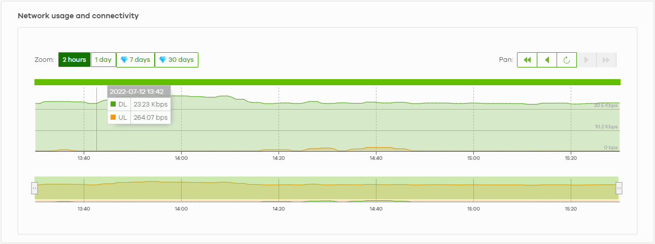
The following table describes the labels in this screen.
Label | Description |
|---|---|
Network usage and connectivity Move the cursor over the chart to see the transmission rate at a specific time. | |
Zoom | Select a time period to view the statistics in the past 2 hours, day, week, or month. |
Pan | Use this to move backward or forward by one day or a week. |