Hardware
The PoE12-3PD has IP55 waterproof and dustproof housing, making it suitable for outdoor installation. The PoE12-3PD’s Ethernet ports have 6kV surge protection.
You can manage and monitor the connected Power Devices using Nebula. If errors occur, reboot the connected Power Devices using Nebula. See NCC Management for more information.
This part describes the ports of the PoE12-3PD and shows you how to make the hardware connections.
See the Quick Start Guide for how to do the hardware installation, mounting, and Internet setup.
Port Connections
The following figures show the ports of the PoE12-3PD.
PoE12-3PD Ports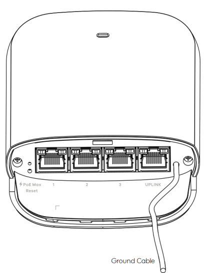
The following table describes the ports.
label | DESCRIPTION |
|---|---|
Port 1 / Port 2 / Port 3 | Connect the ports to an Ethernet device, such as a PoE AP, IP camera or IP phone. |
UPLINK | Connect the port to a PoE switch or PoE injector with power source. |
Grounding and Surge Protection
The PoE12-3PD is an outdoor device with built-in surge protection. However, it must be properly grounded.
Grounding is a safety measure to direct excess electric charge to the ground. It prevents damage to the PoE12-3PD, and protects you from electrocution. Any device that is located outdoors and connected to this product must be properly grounded and surge protected. To the extent permissible by your country’s applicable law, failure to follow these guidelines could result in damage to your PoE12-3PD which may not be covered by its warranty.
 Qualified service personnel must ensure the building’s protective earthing terminals are valid terminals.Note: The protective earthing conductor must be installed by a technician.
Grounding
1 Push down and slide out the device cover.
2 To help protect against lightning and electromagnetic interference, connect the green/yellow ground cable to a grounding bar or on-site grounding terminal.
PoE12-3PD Grounding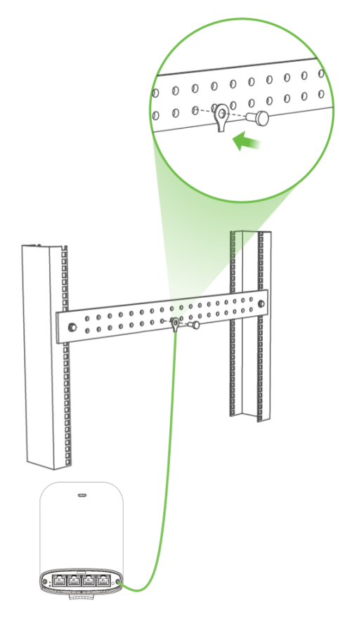
This device must be grounded. Do this before you make other connections.
Surge Protection
For the PoE switch/PoE injector or PDs connected to the PoE12-3PD that lack surge protection, it is recommended to add a surge protector between the PoE12-3PD and the device that needs protection.
In the following figure, the PoE switch (P1) and the IP camera lack surge protection. Place a surge protector (S1) closer to the IP camera to protect it. Place another surge protector (S2) closer to the PoE switch (P1) to protect it.
PoE12-3PD Surge Protection Example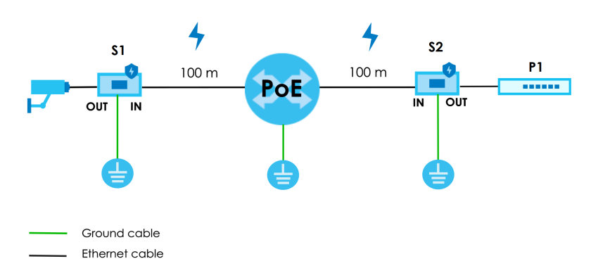
Power Connection
1 Connect the UPLINK port of the PoE12-3PD to a PoE switch or PoE injector that supplies power to the PoE12-3PD.
2 Connect the compatible Ethernet devices requiring power (Powered Devices) to port 1, 2 or 3 of the PoE12-3PD.
3 Gently push each connected Ethernet cable into each slot of the PoE12-3PD cover. Be careful not to damage the cables.
4 Slide the cover back onto the PoE12-3PD until it clicks into place.
Mounting
The following figure shows the back of the PoE12-3PD. See the Quick Start Guide for how to do the wall and pole mounting.
PoE12-3PD Back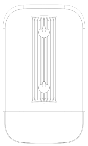
LEDs
The LED Indicators show the current status of the PoE12-3PD. After powering the PoE12-3PD on, see the LEDs to ensure the PoE12-3PD is working properly or diagnose any issues.
The PoE MAX LED shows the remaining PoE power available for the Powered Devices (PDs) connected to ports 1, 2 and 3. The Power MAX LED represents the total power received from the PoE switch or PoE injector through the UPLINK port minus the total power sent to the PDs on ports 1, 2 and 3. See PoE Standards of PoE12-3PD Ports to see the PoE standard of each port.
• PoE MAX = Total PoE In (UPLINK port) - Total PoE Out (ports 1, 2, and 3)
PoE12-3PD LEDs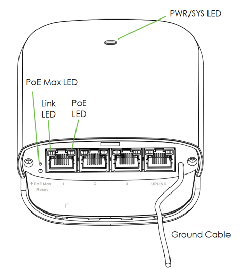
The following table describes the LEDs.
LED | Color | Status | Cloud mode | STANDALONE (ncc discovery disabled) | |
|---|---|---|---|---|---|
PWR/SYS |  | Green | On | The PoE12-3PD is ready to use. | |
 | Blinking | The PoE12-3PD is connected to the NCC but has not been registered with it. | N/A | ||
 | Yellow - Green | Fast Blinking (300ms interval) | The PoE12-3PD is booting. | ||
Slow Blinking (1-second interval) | The PoE12-3PD is trying to connect to the NCC, but the Internet is down. | N/A | |||
 | Yellow | Blinking | The PoE12-3PD is undergoing firmware upgrade. | ||
Off | The power is off. | ||||
PoE MAX |  | Green | On | The remaining power budget is more than 30 Watts. | |
 | Yellow | On | The remaining power budget is between 15.4 and 30 Watts. | ||
 | Slow Blinking (1-second interval) | The remaining power budget is between 7 and 15.4 Watts. | |||
Fast Blinking (300ms interval) | The remaining power budget is between 3.84 and 7 Watts. | ||||
Off | The remaining power budget is less than 3.84 Watts. | ||||
Link/ACT ( left of the ports) |  | Green | On | The 10/100/1000 Mbps connection is ready. | |
 | Blinking | The port is transmitting data at 10/100/1000 Mbps. | |||
Off | No connection or the port is shut down. | ||||
PoE (right of the UPLINK port) |  | Green | On | The port's receiving PoE power is up to 51 Watts (IEEE 802.3bt). | |
 | Yellow | On | The port's receiving PoE power is up to 25.5 /12.95 Watts (IEEE 802.3at/af). | ||
Off | No PoE power is provided. | ||||
PoE (right of ports1-3) |  | Green | On | The supplying PoE power of the port is up to 30 /15.4 Watts (IEEE 802.3at/af). | |
Off | No PoE power is provided. | ||||
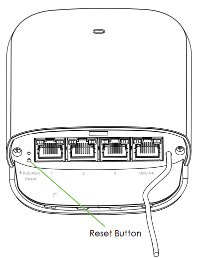
Reset Button
If you forget your password or you cannot access the Web Configurator, you will need to use the Reset button of the PoE12-3PD to reload the factory-default configuration file. This means that you will lose all configurations that you had previously saved, the password will be reset to 1234.
1 Make sure the power LED is on (not blinking).
2 Use a pin to press the Reset button for longer than 5 seconds to set the PoE12-3PD back to its factory-default configurations.
Reset Button of the PoE12-3PD