Classifier
Classifier Overview
This chapter introduces and shows you how to configure the packet classifier on the Switch. It also discusses Quality of Service (QoS) and classifier concepts as employed by the Switch.
What You Can Do
• Use the Classifier Status screen (Classifier Status) to view the classifiers configured on the Switch and how many times the traffic matches the rules.
• Use the Classifier Setup screen (Classifier Setup) to define the classifiers and view a summary of the classifier configuration. After you define the classifier, you can specify actions (or policy) to act upon the traffic that matches the rules.
• Use the Classifier Global Setting screen (Classifier Global Setting) to configure the match order and enable logging on the Switch.
What You Need to Know
Quality of Service (QoS) refers to both a network's ability to deliver data with minimum delay, and the networking methods used to control the use of bandwidth. Without QoS, all traffic data is equally likely to be dropped when the network is congested. This can cause a reduction in network performance and make the network inadequate for time-critical application such as video-on-demand.
A classifier groups traffic into data flows according to specific criteria such as the source address, destination address, source port number, destination port number or incoming port number. For example, you can configure a classifier to select traffic from the same protocol port (such as Telnet) to form a flow.
Configure QoS on the Switch to group and prioritize application traffic and fine-tune network performance. Setting up QoS involves two separate steps:
1 Configure classifiers to sort traffic into different flows.
2 Configure policy rules to define actions to be performed on a classified traffic flow (refer to Policy Rule to configure policy rules).
Classifier Status
Use this screen to view the classifiers configured on the Switch and how many times the traffic matches the rules.
Click SECURITY > ACL > Classifier > Classifier Status to display the configuration screen as shown.
SECURITY > ACL > Classifier > Classifier Status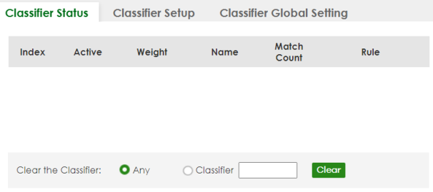
The following table describes the labels in this screen.
label | description |
|---|---|
Index | This field displays the index number of the rule. |
Active | This field displays whether the rule is activated or not. |
Weight | This field displays the rule’s weight. This is to indicate a rule’s priority when the match order is set to manual in the SECURITY > ACL > Classifier > Classifier Global Setting screen. The higher the number, the higher the rule’s priority. |
Name | This field displays the descriptive name for this rule. This is for identification purpose only. |
Match Count | This field displays the number of times a rule is applied. It displays '–' if the rule does not have count enabled. |
Rule | This field displays a summary of the classifier rule’s settings. |
Clear the Classifier | |
Any | Select Any, then click Clear to clear the matched count for all classifiers. |
Classifier | Select Classifier, enter a classifier rule name and then click Clear to erase the recorded statistical information for that classifier, or select Any to clear statistics for all classifiers. |
Clear | Click Clear to erase the recorded statistical information for the classifier. |
Classifier Setup
Use this screen to view and configure the classifiers. After you define the classifier, you can specify actions (or policy) to act upon the traffic that matches the rules.
Click SECURITY > ACL > Classifier Setup to display the configuration screen as shown.
SECURITY > ACL > Classifier > Classifier Setup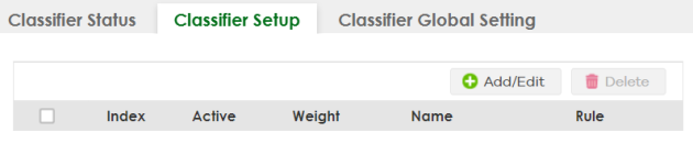
The following table describes the labels in this screen.
label | Description |
|---|---|
Index | This field displays the index number of the rule. |
Active | This field displays Yes when the rule is activated and No when it is deactivated. |
Weight | The field displays the priority of the rule when the match order is in manual mode. A higher weight means a higher priority. |
Name | This field displays the descriptive name for this rule. This is for identification purpose only. |
Rule | This field displays a summary of the classifier rule’s settings. |
Select an entry’s checkbox to select a specific entry. Otherwise, select the checkbox in the table heading row to select all entries. | |
Add/Edit | Click Add/Edit to add a new entry or edit a selected one. |
Delete | Click Delete to remove the selected entries. |
The following table shows some other common Ethernet types and the corresponding protocol number.
ETHERNET TYPE | PROTOCOL NUMBER |
|---|---|
IP ETHII | 0800 |
X.75 Internet | 0801 |
NBS Internet | 0802 |
ECMA Internet | 0803 |
Chaosnet | 0804 |
X.25 Level 3 | 0805 |
XNS Compat | 0807 |
Banyan Systems | 0BAD |
BBN Simnet | 5208 |
IBM SNA | 80D5 |
AppleTalk AARP | 80F3 |
In the Internet Protocol there is a field, called “Protocol”, to identify the next level protocol. The following table shows some common protocol types and the corresponding protocol number. Refer to http://www.iana.org/assignments/protocol-numbers for a complete list.
Protocol TYPE | PROTOCOL NUMBER |
|---|---|
ICMP | 1 |
TCP | 6 |
UDP | 17 |
EGP | 8 |
L2TP | 115 |
Some of the most common TCP and UDP port numbers are:
Protocol NAME | TCP/UDP PORT NUMBER |
|---|---|
FTP | 21 |
Telnet | 23 |
SMTP | 25 |
DNS | 53 |
HTTP | 80 |
POP3 | 110 |
Add/Edit a Classifier
Use this screen to define the classifiers. After you define the classifier, you can specify actions (or policy) to act upon the traffic that matches the rules.
Click Add/Edit, or select an entry and click Add/Edit in the SECURITY > ACL > Classifier Setup screen to display this screen.
SECURITY > ACL > Classifier > Classifier Setup > Add/Edit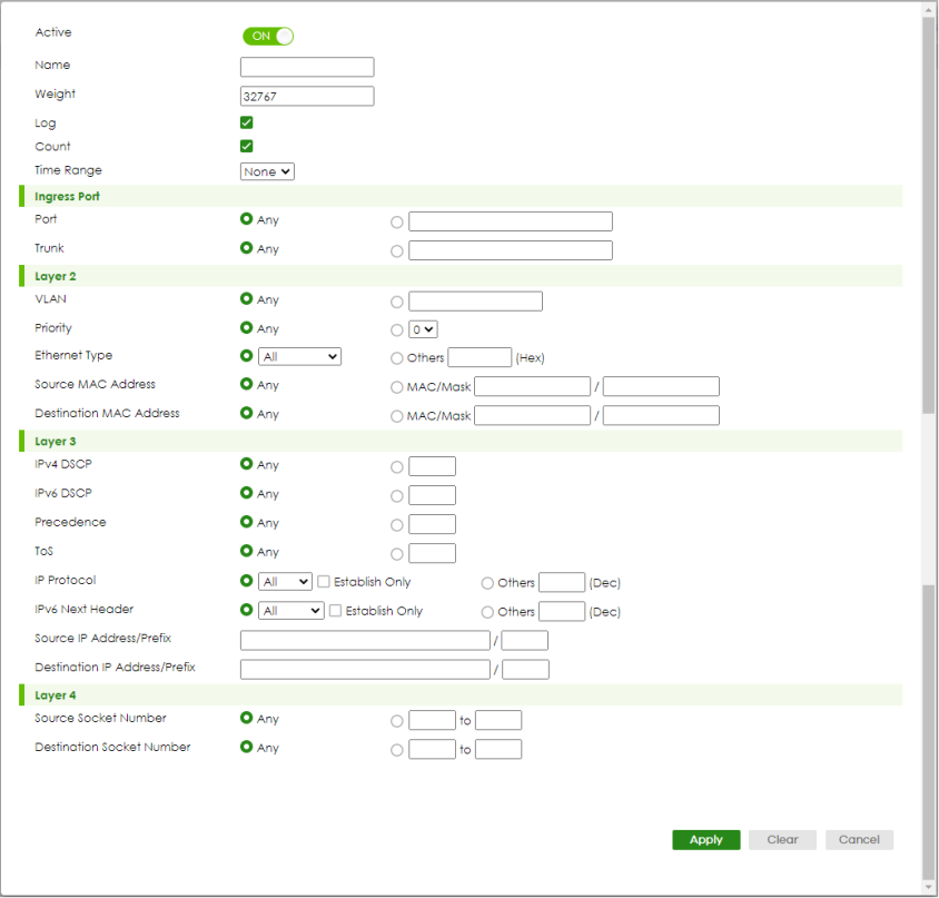
The following table describes the labels in this screen.
label | Description |
|---|---|
Active | Enable the switch button to enable this rule. |
Name | Enter a descriptive name for this rule for identifying purposes. You can enter up to 32 printable ASCII characters except [ ? ], [ | ], [ ' ], [ " ] or [ , ]. |
Weight | Enter a number between 0 and 65535 to specify the rule’s weight. When the match order is in manual mode in the Classifier Global Setting screen, a higher weight means a higher priority. |
Log | Select this option to have the Switch create a log message when the rule is applied and record the number of matched packets in a particular time interval. |
Count | Select this option to have the Switch count how many times the rule is applied. |
Time Range | Select the name of the pre-configured schedule that you want to apply to the rule. The rule will be active only at the scheduled date and/or time. If you select None, the rule will be active all the time. |
Ingress Port | |
Port | Select Any to apply the rule to all ports. Alternatively, to specify the ports enter the port numbers to which the rule should be applied. You can enter multiple ports separ-ated by (no space) comma (,) or hyphen (-). For example, enter “3-5” for ports 3, 4, and 5. Enter “3,5,7” for ports 3, 5, and 7. |
Trunk | Select Any to apply the rule to all trunk groups. Alternatively, to specify multiple trunks, enter the trunk group ID to apply the rule to multiple trunks. You can enter multiple trunks with (t) or (T) then the trunk group ID separated by (no space) comma (,) or hyphen (-). For example, enter “t3-t5” for trunks 3, 4, and 5. Enter “T3,T5,T7” for trunks 3, 5, and 7. |
Layer 2 Specify the fields below to configure a layer 2 classifier. | |
VLAN | Select Any to classify traffic from any VLAN or select the second option and specify the source VLAN ID in the field provided. |
Priority | Select Any to classify traffic from any priority level or select the second option and specify a priority level in the field provided. |
Ethernet Type | Select an Ethernet type or select Other and enter the Ethernet type number in hexadecimal value. |
Source MAC Address | Select Any to apply the rule to all MAC addresses. To specify a source, select MAC/Mask to enter the source MAC address of the packet in valid MAC address format (six hexadecimal character pairs) and type the mask for the specified MAC address to determine which bits a packet’s MAC address should match. Enter “f” for each bit of the specified MAC address that the traffic’s MAC address should match. Enter “0” for the bits of the matched traffic’s MAC address, which can be of any hexadecimal characters. For example, if you set the MAC address to 00:13:49:00:00:00 and the mask to ff:ff:ff:00:00:00, a packet with a MAC address of 00:13:49:12:34:56 matches this criteria. If you leave the Mask field blank, the Switch automatically sets the mask to ff:ff:ff:ff:ff:ff. |
Destination MAC Address | Select Any to apply the rule to all MAC addresses. To specify a destination, select MAC/Mask to enter the destination MAC address of the packet in valid MAC address format (six hexadecimal character pairs) and type the mask for the specified MAC address to determine which bits a packet’s MAC address should match. Enter “f” for each bit of the specified MAC address that the traffic’s MAC address should match. Enter “0” for the bits of the matched traffic’s MAC address, which can be of any hexadecimal characters. For example, if you set the MAC address to 00:13:49:00:00:00 and the mask to ff:ff:ff:00:00:00, a packet with a MAC address of 00:13:49:12:34:56 matches this criteria. If you leave the Mask field blank, the Switch automatically sets the mask to ff:ff:ff:ff:ff:ff. |
Layer 3 Specify the fields below to configure a layer 3 classifier. | |
IPv4/IPv6 DSCP | Select Any to classify traffic from any DSCP or select the second option and specify a DSCP (DiffServ Code Point) number between 0 and 63 in the field provided. |
Precedence | Select Any to classify traffic from any precedence or select the second option and specify an IP Precedence (the first 3 bits of the 8-bit ToS field) value between 0 and 7 in the field provided. |
ToS | Select Any to classify traffic from any ToS or select the second option and specify Type of Service (the last 5 bits of the 8-bit ToS field) value between 0 and 255 in the field provided. |
IP Protocol | Select an IPv4 protocol type or select Other and enter the protocol number in decimal value. You may select Establish Only for TCP protocol type. This means that the Switch will pick out the packets that are sent to establish TCP connections. |
IPv6 Next Header | Select an IPv6 protocol type or select Other and enter an 8-bit next header in the IPv6 packet. The Next Header field is similar to the IPv4 Protocol field. The IPv6 protocol number ranges from 1 to 255. You may select Establish Only for TCP protocol type. This means that the Switch will identify packets that initiate or acknowledge (establish) TCP connections. |
Source IP Address/Address Prefix | Enter a source IP address in dotted decimal notation. Specify the address prefix by entering the number of ones in the subnet mask. A subnet mask can be represented in a 32-bit notation. For example, the subnet mask “255.255.255.0” can be represented as “11111111.11111111.11111111.00000000”, and counting up the number of ones in this case results in 24. |
Destination IP Address/Address Prefix | Enter a destination IP address in dotted decimal notation. Specify the address prefix by entering the number of ones in the subnet mask. |
Layer 4 Specify the fields below to configure a layer 4 classifier. | |
Source Socket Number | Select Any to apply the rule to all TCP/UDP protocol port numbers or select the second option and enter a TCP/UDP protocol port number. |
Destination Socket Number | Select Any to apply the rule to all TCP/UDP protocol port numbers or select the second option and enter a TCP/UDP protocol port number. |
Apply | Click Apply to save your changes to the Switch’s run-time memory. The Switch loses these changes if it is turned off or loses power, so use the Save link on the top navigation panel to save your changes to the non-volatile memory when you are done configuring. |
Clear | Click Clear to clear the fields to the factory defaults. |
Cancel | Click Cancel to not save the configuration you make and return to the last screen. |
Classifier Global Setting
Use this screen to configure the match order and enable logging on the Switch. Click SECURITY > ACL > Classifier > Classifier Global Setting to display the configuration screen as shown.
SECURITY > ACL > Classifier > Classifier Global Setting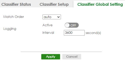
The following table describes the labels in this screen.
label | Description |
|---|---|
Match Order | Use this field to set the match order for the classifier rules. A traffic flow can only be classified to one classifier. When a traffic flow matches more than one classifier rule, the Switch classifies the traffic based on the Match Order. Select manual to have classifier rules applied according to the weight of each rule you configured in SECURITY > ACL > Classifier > Classifier Setup. If they have the same weight, the Switch will classify the traffic to the classifier with a higher name priority (see Classifier Name Priority). Alternatively, select auto to have classifier rules applied according to the layer of the item configured in the rule. Layer-4 items have the highest priority, and layer-2 items has the lowest priority. For example, you configure a layer-2 item (VLAN ID) in classifier A and configure a layer-3 item (source IP address) in classifier B. When an incoming packet matches both classifier rules, classifier B has priority over classifier A. If both classifiers have the same priority, the Switch will apply the classifier with a higher name priority. Classifier Name Priority The longer the classifier name, the higher the classifier priority. If two classifier names are the same length, the bigger the character, the higher the classifier priority. The lowercase letters (such as a and b) have higher priority than the capitals (such as A and B) in the classifier name. For example, the classifier with the name of class 2, class a or class B takes priority over the classifier with the name of class 1 or class A. |
Logging | |
Active | Enable the switch button to allow the Switch to create a log when packets match a classifier rule during a defined time interval. |
Interval | Set the length of the time period (in seconds) to count matched packets for a classifier rule. Enter an integer from 0 – 65535. 0 means that no logging is done. |
Apply | Click Apply to save your changes to the Switch’s run-time memory. The Switch loses these changes if it is turned off or loses power, so use the Save link on the top navigation panel to save your changes to the non-volatile memory when you are done configuring. |
Cancel | Click Cancel to begin configuring this screen afresh. |
Classifier Example
The following screen shows an example where you configure a classifier that identifies all traffic from MAC address 00:50:ba:ad:4f:81 on port 2.
Classifier: Example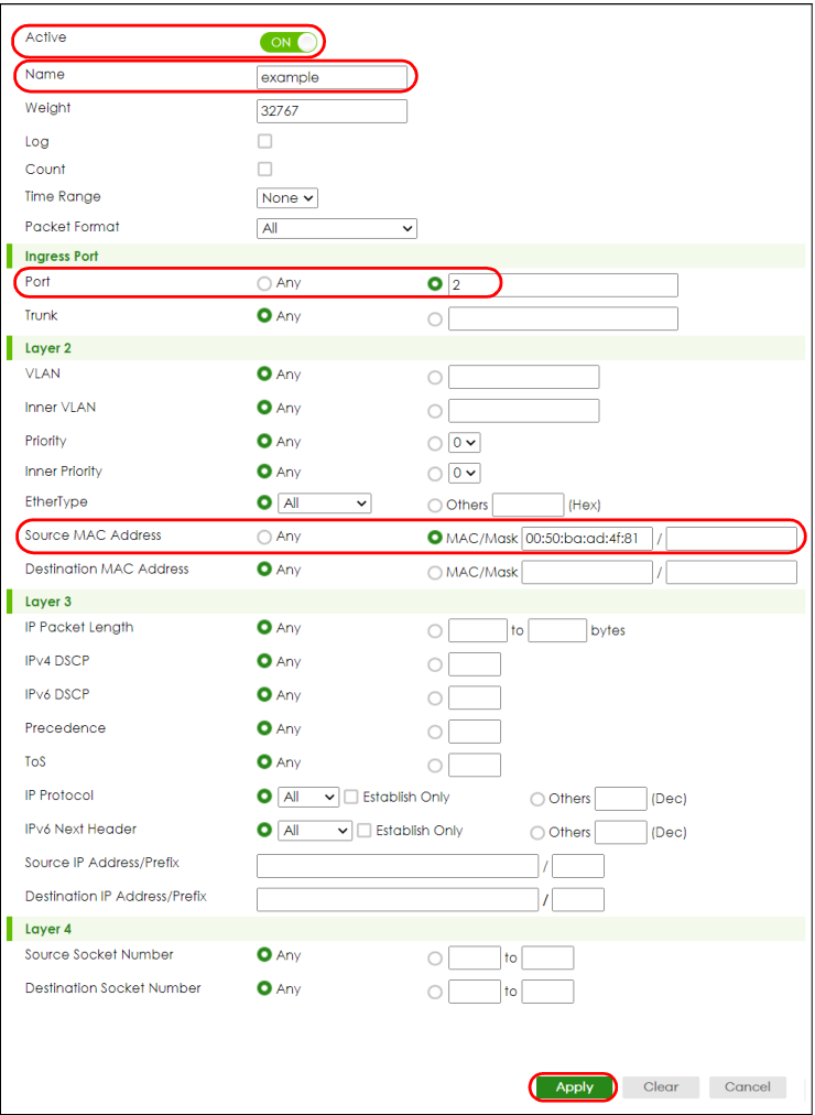
After you have configured a classifier, you can configure a policy (in the SECURITY > ACL > Policy Rule screen) to define actions on the classified traffic flow.