Layer 2 Protocol Tunneling
Layer 2 Protocol Tunneling Overview
This chapter shows you how to configure layer 2 protocol tunneling on the Switch.
What You Can Do
Use the Layer 2 Protocol Tunneling screen (Configuring Layer 2 Protocol Tunneling) to enable layer 2 protocol tunneling on the Switch and specify a MAC address with which the Switch uses to encapsulate the layer 2 protocol packets by replacing the destination MAC address in the packets.
What You Need to Know
Layer 2 protocol tunneling (L2PT) is used on the service provider's edge devices.
L2PT allows edge switches (1 and 2 in the following figure) to tunnel layer 2 STP (Spanning Tree Protocol), CDP (Cisco Discovery Protocol) and VTP (VLAN Trunking Protocol) packets between customer switches (A, B and C in the following figure) connected through the service provider’s network. The edge switch encapsulates layer 2 protocol packets with a specific MAC address before sending them across the service provider’s network to other edge switches.
Layer 2 Protocol Tunneling Network Scenario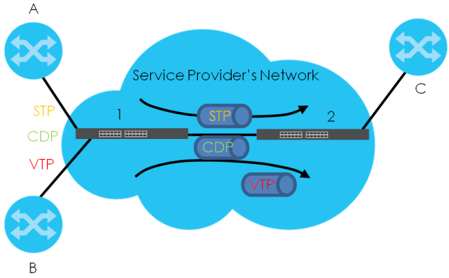
In the following example, if you enable L2PT for STP, you can have switches A, B, C and D in the same spanning tree, even though switch A is not directly connected to switches B, C and D. Topology change information can be propagated throughout the service provider’s network.
To emulate a point-to-point topology between two customer switches at different sites, such as A and B, you can enable protocol tunneling on edge switches 1 and 2 for PAgP (Port Aggregation Protocol), LACP or UDLD (Uni-Directional Link Detection).
L2PT Network Example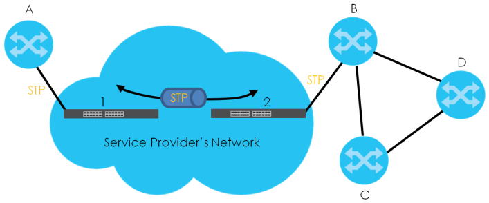
Layer 2 Protocol Tunneling Mode
Each port can have two layer 2 protocol tunneling modes, Access and Tunnel.
• The Access port is an ingress port on the service provider's edge device (1 or 2 in L2PT Network Example) and connected to a customer switch (A or B). Incoming layer 2 protocol packets received on an access port are encapsulated and forwarded to the tunnel ports.
• The Tunnel port is an egress port at the edge of the service provider's network and connected to another service provider’s switch. Incoming encapsulated layer 2 protocol packets received on a tunnel port are decapsulated and sent to an access port.
Configuring Layer 2 Protocol Tunneling
Click SWITCHING > Layer 2 Protocol Tunneling in the navigation panel to display the screen as shown.
SWITCHING > Layer 2 Protocol Tunneling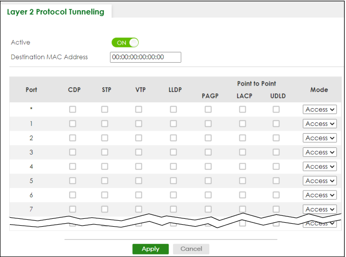
The following table describes the labels in this screen.
label | description |
|---|---|
Active | Enable the switch button to enable layer 2 protocol tunneling on the Switch. |
Destination MAC Address | Specify a MAC address with which the Switch uses to encapsulate the layer 2 protocol packets by replacing the destination MAC address in the packets. |
Port | This field displays the port number. * means all ports. |
* | Use this row to make the setting the same for all ports. Use this row first and then make adjustments on a port-by-port basis. |
CDP | Select this option to have the Switch tunnel CDP (Cisco Discovery Protocol) packets so that other Cisco devices can be discovered through the service provider’s network. |
STP | Select this option to have the Switch tunnel STP (Spanning Tree Protocol) packets so that STP can run properly across the service provider’s network and spanning trees can be set up based on bridge information from all (local and remote) networks. |
VTP | Select this option to have the Switch tunnel VTP (VLAN Trunking Protocol) packets so that all customer switches can use consistent VLAN configuration through the service provider’s network. |
LLDP | Select this option to have the Switch tunnel LLDP (Link Layer Discovery Protocol) packets so that all network devices can advertise its identity and capabilities through the service provider’s network. |
Point to Point | The Switch supports PAgP (Port Aggregation Protocol), LACP (Link Aggregation Control Protocol) and UDLD (UniDirectional Link Detection) tunneling for a point-to-point topology. Both PAgP and UDLD are Cisco’s proprietary data link layer protocols. PAgP is similar to LACP and used to set up a logical aggregation of Ethernet ports automatically. UDLD is to determine the link’s physical status and detect a unidirectional link. |
PAGP | Select this option to have the Switch send PAgP packets to a peer to automatically negotiate and build a logical port aggregation. |
LACP | Select this option to have the Switch send LACP packets to a peer to dynamically create and manage trunk groups. |
UDLD | Select this option to have the Switch send UDLD packets to a peer’s port it connected to monitor the physical status of a link. |
Mode | Select Access to have the Switch encapsulate the incoming layer 2 protocol packets and forward them to the tunnel ports. Select Access for ingress ports at the edge of the service provider's network. Select Tunnel for egress ports at the edge of the service provider's network. The Switch decapsulates the encapsulated layer 2 protocol packets received on a tunnel port by changing the destination MAC address to the original one, and then forward them to an access port. If the services is not enabled on an access port, the protocol packets are dropped. |
Apply | Click Apply to save your changes to the Switch’s run-time memory. The Switch loses these changes if it is turned off or loses power, so use the Save link on the top navigation panel to save your changes to the non-volatile memory when you are done configuring. |
Cancel | Click Cancel to begin configuring this screen afresh. |