Spanning Tree Protocol
Spanning Tree Protocol Overview
The Switch supports Spanning Tree Protocol (STP), Rapid Spanning Tree Protocol (RSTP) and Multiple Spanning Tree Protocol (MSTP) as defined in the following standards.
• IEEE 802.1D Spanning Tree Protocol
• IEEE 802.1w Rapid Spanning Tree Protocol
The Switch also allows you to set up multiple STP configurations (or trees). Ports can then be assigned to the trees.
What You Can Do
• Use the Spanning Tree Protocol Status screen (Spanning Tree Protocol Status) to view the STP status in the different STP modes (RSTP or MSTP) you can configure on the Switch.
• Use the Spanning Tree Setup screen (Spanning Tree Setup) to activate one of the STP modes on the Switch.
• Use the Rapid Spanning Tree Protocol Status screen (Rapid Spanning Tree Protocol Status) to view the RSTP status.
• Use the Rapid Spanning Tree Protocol screen (Configure Rapid Spanning Tree Protocol) to configure RSTP settings.
• Use the Multiple Spanning Tree Protocol Status screen (Multiple Spanning Tree Protocol Status) to view the MSTP status.
• Use the Multiple Spanning Tree Protocol screen (Configure Multiple Spanning Tree Protocol) to configure MSTP.
• Use the Multiple Spanning Tree Protocol Port Setup screen (Multiple Spanning Tree Protocol Port Setup) to configure MSTP ports.
What You Need to Know
Read on for concepts on STP that can help you configure the screens in this chapter.
(Rapid) Spanning Tree Protocol
(R)STP detects and breaks network loops and provides backup links between switches, bridges or routers. It allows a switch to interact with other (R)STP-compliant switches in your network to ensure that only one path exists between any two stations on the network.
The Switch uses IEEE 802.1w RSTP (Rapid Spanning Tree Protocol) that allows faster convergence of the spanning tree than STP (while also being backwards compatible with STP-only aware bridges). In RSTP, topology change information is directly propagated throughout the network from the device that generates the topology change. In STP, a longer delay is required as the device that causes a topology change first notifies the root bridge that then notifies the network. Both RSTP and STP flush unwanted learned addresses from the filtering database. In RSTP, the port states are Discarding, Learning, and Forwarding.
STP Terminology
The root bridge is the base of the spanning tree.
Path cost is the cost of transmitting a frame onto a LAN through that port. The recommended cost is assigned according to the speed of the link to which a port is attached. The slower the media, the higher the cost.
Link Speed | Recommended value | Recommended range | Allowed Range | |
|---|---|---|---|---|
Path Cost | 4 Mbps | 250 | 100 to 1000 | 1 to 65535 |
Path Cost | 10 Mbps | 100 | 50 to 600 | 1 to 65535 |
Path Cost | 16 Mbps | 62 | 40 to 400 | 1 to 65535 |
Path Cost | 100 Mbps | 19 | 10 to 60 | 1 to 65535 |
Path Cost | 1 Gbps | 4 | 3 to 10 | 1 to 65535 |
Path Cost | 10 Gbps | 2 | 1 to 5 | 1 to 65535 |
On each bridge, the root port is the port through which this bridge communicates with the root. It is the port on this switch with the lowest path cost to the root (the root path cost). If there is no root port, then this switch has been accepted as the root bridge of the spanning tree network.
For each LAN segment, a designated bridge is selected. This bridge has the lowest cost to the root among the bridges connected to the LAN.
How STP Works
After a bridge determines the lowest cost-spanning tree with STP, it enables the root port and the ports that are the designated ports for connected LANs, and disables all other ports that participate in STP. Network packets are therefore only forwarded between enabled ports, eliminating any possible network loops.
STP-aware switches exchange Bridge Protocol Data Units (BPDUs) periodically. When the bridged LAN topology changes, a new spanning tree is constructed.
Once a stable network topology has been established, all bridges listen for Hello BPDUs (Bridge Protocol Data Units) transmitted from the root bridge. If a bridge does not get a Hello BPDU after a predefined interval (Max Age), the bridge assumes that the link to the root bridge is down. This bridge then initiates negotiations with other bridges to reconfigure the network to re-establish a valid network topology.
STP Port States
STP assigns five port states to eliminate packet looping. A bridge port is not allowed to go directly from blocking state to forwarding state so as to eliminate transient loops.
Port State | Description |
|---|---|
Disabled | STP is disabled (default). |
Blocking | Only configuration and management BPDUs are received and processed. |
Listening | All BPDUs are received and processed. |
Learning | All BPDUs are received and processed. Information frames are submitted to the learning process but not forwarded. |
Forwarding | All BPDUs are received and processed. All information frames are received and forwarded. |
Multiple STP
Multiple Spanning Tree Protocol (IEEE 802.1s) is backward compatible with STP/RSTP and addresses the limitations of existing spanning tree protocols (STP and RSTP) in networks to include the following features:
• One Common and Internal Spanning Tree (CIST) that represents the entire network’s connectivity.
• Grouping of multiple bridges (or switching devices) into regions that appear as one single bridge on the network.
• A VLAN can be mapped to a specific Multiple Spanning Tree Instance (MSTI). MSTI allows multiple VLANs to use the same spanning tree.
• Load-balancing is possible as traffic from different VLANs can use distinct paths in a region.
Spanning Tree Protocol Status
The Spanning Tree Protocol status screen changes depending on what standard you choose to implement on your network. Click SWITCHING > Spanning Tree Protocol > Spanning Tree Protocol Status to see the screen as shown.
SWITCHING > Spanning Tree Protocol > Spanning Tree Protocol Status 
This screen differs depending on which STP mode (RSTP or MSTP) you configure on the Switch. This screen is described in detail in the section that follows the configuration section for each STP mode. Use the SWITCHING > Spanning Tree Protocol > Spanning Tree Setup screen to activate one of the STP standards on the Switch.
Spanning Tree Setup
Use the this screen to activate one of the STP modes on the Switch. Click SWITCHING > Spanning Tree Protocol > Spanning Tree Setup to display the screen as shown.
SWITCHING > Spanning Tree Protocol > Spanning Tree Setup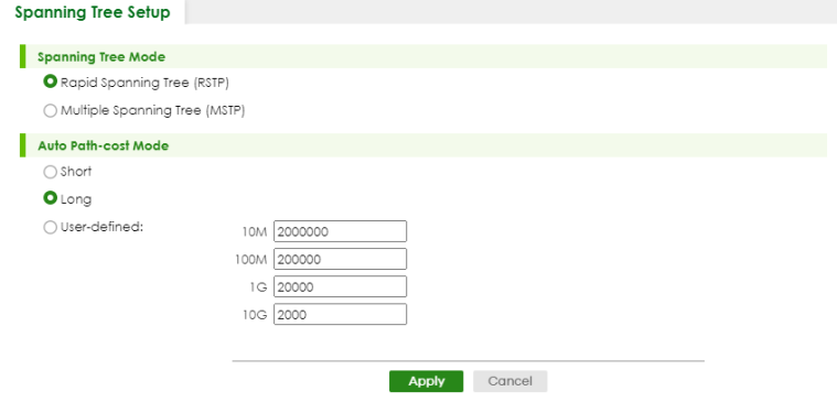
The following table describes the labels in this screen.
label | description |
|---|---|
Spanning Tree Mode | You can activate one of the STP modes on the Switch. Select Rapid Spanning Tree or Multiple Spanning Tree. |
Auto Path-cost Mode Auto Path-cost Mode allows you to have the Switch automatically set the path cost for each port according to their link speed. The Switch uses the path costs to determine the best path to the root bridge in a spanning tree. There are three Auto Path-cost Modes that supports different path cost lengths: • Short (16-bit) • Long (32-bit) • User-defined (32-bit). The auto path cost values of each mode are described in Spanning Tree Setup. To use the auto path-cost feature, select the Auto Path-cost mode (Short, Long, User-defined), set a port’s Path Cost (in the SWITCHING > Spanning Tree Protocol > RSTP and MSTP screens) to “0”. The Switch will automatically set the port’s path cost to the auto path cost value defined by the Auto Path-cost Mode you select. | |
Short | Select this mode if you want to use the 16-bit auto path cost values the Switch defines. |
Long | Select this mode if you want to use the 32-bit auto path cost values the Switch defines. |
User-defined | Select this mode to manually set the auto path costs for each link speed. Enter the path cost value for each link speed. The range is from 1 – 2000000. It is recommended to assign this value according to link speeds. The slower the speed, the higher the cost. |
Apply | Click Apply to save your changes to the Switch’s run-time memory. The Switch loses these changes if it is turned off or loses power, so use the Save link on the top navigation panel to save your changes to the non-volatile memory when you are done configuring. |
Cancel | Click Cancel to begin configuring this screen afresh. |
Rapid Spanning Tree Protocol Status
The Spanning Tree Protocol status screen changes depending on what standard you choose to implement on your network. Click SWITCHING > Spanning Tree Protocol > Spanning Tree Protocol Status in the navigation panel to display the status screen as shown next. See Spanning Tree Protocol Overview for more information on RSTP.
SWITCHING > Spanning Tree Protocol > Spanning Tree Protocol Status: RSTP 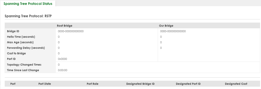
SWITCHING > Spanning Tree Protocol > Spanning Tree Protocol Status: RSTP (Cloud Mode)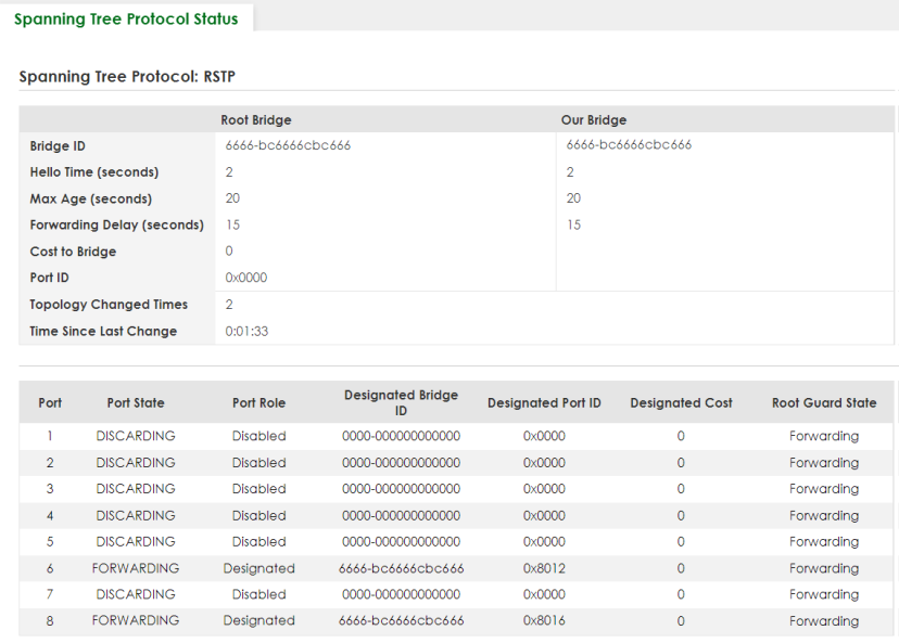
The following table describes the labels in this screen.
LABEL | DESCRIPTION |
|---|---|
Bridge | Root Bridge refers to the base of the spanning tree (the root bridge). Our Bridge is this Switch. This Switch may also be the root bridge. |
Bridge ID | This is the unique identifier for this bridge, consisting of bridge priority plus MAC address. This ID is the same for Root Bridge and Our Bridge if the Switch is the root switch. |
Hello Time (seconds) | This is the time interval (in seconds) at which the root switch transmits a configuration message. The root bridge determines Hello Time, Max Age and Forwarding Delay. |
Max Age (seconds) | This is the maximum time (in seconds) the Switch can wait without receiving a configuration message before attempting to reconfigure. |
Forwarding Delay (seconds) | This is the time (in seconds) the root switch will wait before changing states (that is, listening to learning to forwarding). |
Cost to Bridge | This is the path cost from the root port on this Switch to the root switch. |
Port ID | This is the priority and number of the port on the Switch through which this Switch must communicate with the root of the Spanning Tree. |
Topology Changed Times | This is the number of times the spanning tree has been reconfigured. |
Time Since Last Change | This is the time since the spanning tree was last reconfigured. |
Port | This field displays the number of the port on the Switch. |
Port State | This field displays the port state in STP. • DISCARDING – The port does not forward or process received frames or learn MAC addresses, but still listens for BPDUs. • LEARNING – The port learns MAC addresses and processes BPDUs, but does NOT forward frames yet. • FORWARDING – The port is operating normally. It learns MAC addresses, processes BPDUs and forwards received frames. |
Port Role | This field displays the role of the port in STP. • Root – A forwarding port on a non-root bridge, which has the lowest path cost and is the best port from the non-root bridge to the root bridge. A root bridge does NOT have a root port. • Designated – A forwarding port on the designated bridge for each connected LAN segment. A designated bridge has the lowest path cost to the root bridge among the bridges connected to the LAN segment. All the ports on a root bridge (root switch) are designated ports. • Alternate – A blocked port, which has a best alternate path to the root bridge. This path is different from using the root port. The port moves to the forwarding state when the designated port for the LAN segment fails. • Backup – A blocked port, which has a backup or redundant path to a LAN segment where a designated port is already connected when a switch has two links to the same LAN segment. • Disabled – Not strictly part of STP. The port can be disabled manually. |
Designated Bridge ID | This field displays the identifier of the designated bridge to which this port belongs when the port is a designated port. Otherwise, it displays the identifier of the designated bridge for the LAN segment to which this port is connected. |
Designated Port ID | This field displays the priority and number of the bridge port (on the designated bridge), through which the designated bridge transmits the stored configuration messages. |
Designated Cost | This field displays the path cost to the LAN segment to which the port is connected when the port is a designated port. Otherwise, it displays the path cost to the root bridge from the designated port for the LAN segment to which this port is connected. |
Root Guard State | This field displays the state of the port on which root guard is enabled. • Root-inconsistent – the Switch receives superior BPDUs on the port and blocks the port. • Forwarding – the Switch unblocks and allows the port to forward frames again. |
Configure Rapid Spanning Tree Protocol
Use this screen to configure RSTP settings, see Spanning Tree Protocol Overview for more information on RSTP. Click SWITCHING > Spanning Tree Protocol > RSTP in the navigation panel to display the screen as shown.
SWITCHING > Spanning Tree Protocol > RSTP 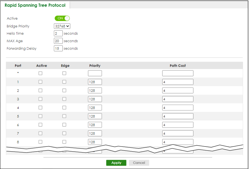
SWITCHING > Spanning Tree Protocol > RSTP (Cloud Mode)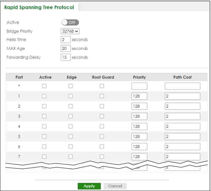
The following table describes the labels in this screen.
label | description |
|---|---|
Active | Enable the switch button to activate RSTP. Disable the switch to disable RSTP. |
Bridge Priority | Bridge priority is used in determining the root switch, root port and designated port. The Switch with the highest priority (lowest numeric value) becomes the STP root switch. If all Switches have the same priority, the Switch with the lowest MAC address will then become the root switch. Select a value from the drop-down list box. The lower the numeric value you assign, the higher the priority for this bridge. Bridge Priority determines the root bridge, which in turn determines Hello Time, Max Age and Forwarding Delay. |
Hello Time | This is the time interval in seconds between BPDU (Bridge Protocol Data Units) configuration message generations by the root switch. The allowed range is 1 to 10 seconds. |
Max Age | This is the maximum time (in seconds) the Switch can wait without receiving a BPDU before attempting to reconfigure. All Switch ports (except for designated ports) should receive BPDUs at regular intervals. Any port that ages out STP information (provided in the last BPDU) becomes the designated port for the attached LAN. If it is a root port, a new root port is selected from among the Switch ports attached to the network. The allowed range is 6 to 40 seconds. |
Forwarding Delay | This is the maximum time (in seconds) the Switch will wait before changing states. This delay is required because every Switch must receive information about topology changes before it starts to forward frames. In addition, each port needs time to listen for conflicting information that would make it return to a blocking state; otherwise, temporary data loops might result. The allowed range is 4 to 30 seconds. As a general rule: 2 * (Forward Delay – 1) >= Max Age >= 2 * (Hello Time + 1) |
Port | This field displays the port number. |
* | Settings in this row apply to all ports. Use this row only if you want to make some settings the same for all ports. Use this row first to set the common settings and then make adjustments on a port-by-port basis. |
Active | Select this checkbox to activate RSTP on this port. |
Edge | Select this checkbox to configure a port as an edge port when it is directly attached to a computer. An edge port changes its initial STP port state from blocking state to forwarding state immediately without going through listening and learning states right after the port is configured as an edge port or when its link status changes. |
Root Guard | Select this checkbox to enable root guard on this port in order to prevent the switches attached to the port from becoming the root bridge. With root guard enabled, a port is blocked when the Switch receives a superior BPDU on it. The Switch allows traffic to pass through this port again when the switch connected to the port stops to send superior BPDUs. |
Priority | Configure the priority for each port here. Priority decides which port should be disabled when more than one port forms a loop in a switch. Ports with a higher priority numeric value are disabled first. The allowed range is between 0 and 255 and the default value is 128. |
Path Cost | Path cost is the cost of transmitting a frame on to a LAN through that port. It is recommended to assign this value according to the speed of the bridge. The slower the media, the higher the cost. |
Apply | Click Apply to save your changes to the Switch’s run-time memory. The Switch loses these changes if it is turned off or loses power, so use the Save link on the top navigation panel to save your changes to the non-volatile memory when you are done configuring. |
Cancel | Click Cancel to begin configuring this screen afresh. |
Multiple Spanning Tree Protocol Status
Click SWITCHING > Spanning Tree Protocol > Spanning Tree Protocol Status in the navigation panel to display the status screen as shown next.
SWITCHING > Spanning Tree Protocol > Spanning Tree Protocol Status: MSTP 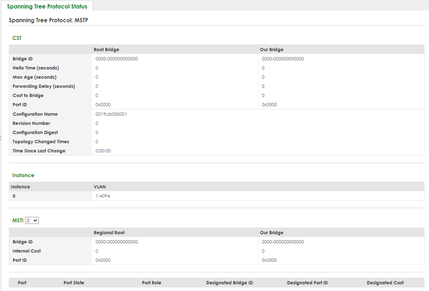
SWITCHING > Spanning Tree Protocol > Spanning Tree Protocol Status: MSTP (Cloud Mode)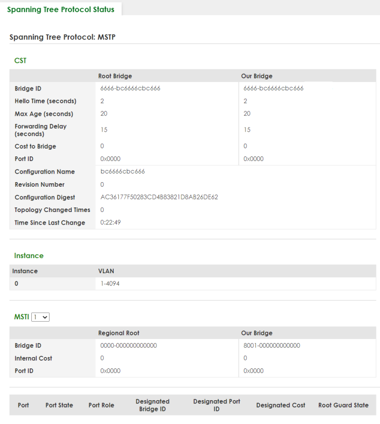
The following table describes the labels in this screen.
LABEL | DESCRIPTION |
|---|---|
CST This section describes the Common Spanning Tree settings. | |
Bridge | Root Bridge refers to the base of the spanning tree (the root bridge). Our Bridge is this switch. This Switch may also be the root bridge. |
Bridge ID | This is the unique identifier for this bridge, consisting of bridge priority plus MAC address. This ID is the same for Root Bridge and Our Bridge if the Switch is the root switch. |
Hello Time (seconds) | This is the time interval (in seconds) at which the root switch transmits a configuration message. The root bridge determines Hello Time, Max Age and Forwarding Delay. |
Max Age (seconds) | This is the maximum time (in seconds) the Switch can wait without receiving a configuration message before attempting to reconfigure. |
Forwarding Delay (seconds) | This is the time (in seconds) the root switch will wait before changing states (that is, listening to learning to forwarding). |
Cost to Bridge | This is the path cost from the root port on this Switch to the root switch. |
Port ID | This is the priority and number of the port on the Switch through which this Switch must communicate with the root of the Spanning Tree. |
Configuration Name | This field displays the configuration name for this MST region. |
Revision Number | This field displays the revision number for this MST region. |
Configuration Digest | A configuration digest is generated from the VLAN-MSTI mapping information. This field displays the 16-octet signature that is included in an MSTP BPDU. This field displays the digest when MSTP is activated on the system. |
Topology Changed Times | This is the number of times the spanning tree has been reconfigured. |
Time Since Last Change | This is the time since the spanning tree was last reconfigured. |
Instance | These fields display the MSTI to VLAN mapping. In other words, which VLANs run on each spanning tree instance. |
Instance | This field displays the MSTI ID. |
VLAN | This field displays which VLANs are mapped to an MSTI. |
MSTI | |
MSTI | Select the MST instance settings you want to view. |
Regional Root refers to the base of the MST instance. Our Bridge is this switch. This Switch may also be the root bridge. | |
Bridge ID | This is the unique identifier for this bridge, consisting of bridge priority plus MAC address. This ID is the same for Regional Root and Our Bridge if the Switch is the root switch. |
Internal Cost | This is the path cost from the root port in this MST instance to the regional root switch. |
Port ID | This is the priority and number of the port on the Switch through which this Switch must communicate with the root of the MST instance. |
Port | This field displays the number of the port on the Switch. |
Port State | This field displays the port state in STP. • DISCARDING – The port does not forward or process received frames or learn MAC addresses, but still listens for BPDUs. • LEARNING – The port learns MAC addresses and processes BPDUs, but does not forward frames yet. • FORWARDING – The port is operating normally. It learns MAC addresses, processes BPDUs and forwards received frames. |
Port Role | This field displays the role of the port in STP. • Root – A forwarding port on a non-root bridge, which has the lowest path cost and is the best port from the non-root bridge to the root bridge. A root bridge does not have a root port. • Designated – A forwarding port on the designated bridge for each connected LAN segment. A designated bridge has the lowest path cost to the root bridge among the bridges connected to the LAN segment. All the ports on a root bridge (root switch) are designated ports. • Alternate – A blocked port, which has a best alternate path to the root bridge. This path is different from using the root port. The port moves to the forwarding state when the designated port for the LAN segment fails. • Backup – A blocked port, which has a backup or redundant path to a LAN segment where a designated port is already connected when a switch has two links to the same LAN segment. • Disabled – Not strictly part of STP. The port can be disabled manually. |
Designated Bridge ID | This field displays the identifier of the designated bridge to which this port belongs when the port is a designated port. Otherwise, it displays the identifier of the designated bridge for the LAN segment to which this port is connected. |
Designated Port ID | This field displays the priority and number of the bridge port (on the designated bridge), through which the designated bridge transmits the stored configuration messages. |
Designated Cost | This field displays the path cost to the LAN segment to which the port is connected when the port is a designated port. Otherwise, it displays the path cost to the root bridge from the designated port for the LAN segment to which this port is connected. |
Root Guard State | This field displays the state of the port on which root guard is enabled. • Root-inconsistent – the Switch receives superior BPDUs on the port and blocks the port. • Forwarding – the Switch unblocks and allows the port to forward frames again. |
Configure Multiple Spanning Tree Protocol
To configure MSTP, click SWITCHING > Spanning Tree Protocol > MSTP in the navigation panel to display the screen as shown.
SWITCHING > Spanning Tree Protocol > MSTP > Multiple Spanning Tree Protocol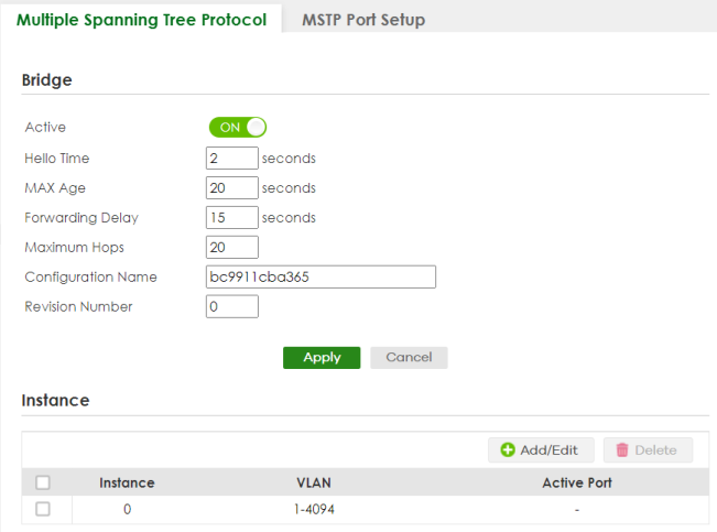
The following table describes the labels in this screen.
label | description |
|---|---|
Bridge | |
Active | Enable the switch button to activate MSTP on the Switch. Disable the switch to disable MSTP on the Switch. |
Hello Time | This is the time interval in seconds between BPDU (Bridge Protocol Data Units) configuration message generations by the root switch. The allowed range is 1 to 10 seconds. |
Max Age | This is the maximum time (in seconds) a switch can wait without receiving a BPDU before attempting to reconfigure. All switch ports (except for designated ports) should receive BPDUs at regular intervals. Any port that ages out STP information (provided in the last BPDU) becomes the designated port for the attached LAN. If it is a root port, a new root port is selected from among the Switch ports attached to the network. The allowed range is 6 to 40 seconds. |
Forwarding Delay | This is the maximum time (in seconds) a switch will wait before changing states. This delay is required because every switch must receive information about topology changes before it starts to forward frames. In addition, each port needs time to listen for conflicting information that would make it return to a blocking state; otherwise, temporary data loops might result. The allowed range is 4 to 30 seconds. As a general rule: |
Maximum hops | Enter the number of hops (between 1 and 255) in an MSTP region before the BPDU is discarded and the port information is aged. |
Configuration Name | Enter a descriptive name (up to 32 printable ASCII characters except [ ? ], [ | ], [ ' ], [ " ], or [ , ]) of an MST region. |
Revision Number | Enter a number to identify a region’s configuration. Devices must have the same revision number to belong to the same region. |
Apply | Click Apply to save your changes to the Switch’s run-time memory. The Switch loses these changes if it is turned off or loses power, so use the Save link on the top navigation panel to save your changes to the non-volatile memory when you are done configuring. |
Cancel | Click Cancel to begin configuring this screen afresh. |
Instance Use this section to configure MSTI (Multiple Spanning Tree Instance) settings. | |
Instance | This field displays the ID of an MST instance. |
VLAN | This field displays the VID (or VID ranges) to which the MST instance is mapped. |
Active Port | This field display the ports configured to participate in the MST instance. |
Select an entry’s checkbox to select a specific entry. Otherwise, select the checkbox in the table heading row to select all entries. | |
Add/Edit | Click Add/Edit to add a new instance or edit a selected one. |
Delete | Click Delete to remove the selected instances. |
Add/Edit Multiple Spanning Tree
Click Add/Edit, or select an entry and click Add/Edit in the SWITCHING > Spanning Tree Protocol > MSTP > Multiple Spanning Tree Protocol screen to display this screen.
SWITCHING > Spanning Tree Protocol > MSTP > Multiple Spanning Tree Protocol > Add/Edit
The following table describes the labels in this screen.
label | description |
|---|---|
Instance | Enter the number you want to use to identify this MST instance on the Switch. The Switch supports instance numbers 0 – 16. |
Bridge Priority | Set the priority of the Switch for the specific spanning tree instance. The lower the number, the more likely the Switch will be chosen as the root bridge within the spanning tree instance. Enter priority values between 0 and 61440 in increments of 4096 (thus valid values are 4096, 8192, 12288, 16384, 20480, 24576, 28672, 32768, 36864, 40960, 45056, 49152, 53248, 57344 and 61440). |
VLAN List | Enter the VLAN ID range. You can specify multiple VLAN ID range separated by (no space) comma (,) or hyphen (“-”) for a range. For example, enter “1,3,5-7” for VLANs 1, 3, 5, 6, and 7. |
Port | This field displays the port number. * means all ports. |
* | Settings in this row apply to all ports. Use this row only if you want to make some settings the same for all ports. Use this row first to set the common settings and then make adjustments on a port-by-port basis. |
Active | Select this checkbox to add this port to the MST instance. |
Priority | Configure the priority for each port here. Priority decides which port should be disabled when more than one port forms a loop in the Switch. Ports with a higher priority numeric value are disabled first. The allowed range is between 0 and 255 and the default value is 128. |
Path Cost | Path cost is the cost of transmitting a frame on to a LAN through that port. It is recommended to assign this value according to the speed of the bridge. The slower the media, the higher the cost. |
Apply | Click Apply to save your changes to the Switch’s run-time memory. The Switch loses these changes if it is turned off or loses power, so use the Save link on the top navigation panel to save your changes to the non-volatile memory when you are done configuring. |
Clear | Click Clear to clear the fields to the factory defaults. |
Cancel | Click Cancel to not save the configuration you make and return to the last screen. |
Multiple Spanning Tree Protocol Port Setup
Click SWITCHING > Spanning Tree Protocol > MSTP > MSTP Port Setup to display the screen as shown next.
SWITCHING > Spanning Tree Protocol > MSTP > MSTP Port Setup 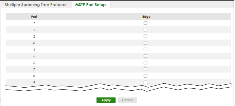
SWITCHING > Spanning Tree Protocol > MSTP > MSTP Port Setup (Cloud Mode)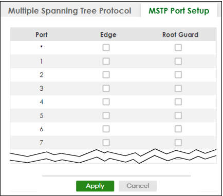
The following table describes the labels in this screen.
LABEL | DESCRIPTION |
|---|---|
Port | This field displays the port number. * means all ports. |
* | Settings in this row apply to all ports. Use this row only if you want to make some settings the same for all ports. Use this row first to set the common settings and then make adjustments on a port-by-port basis. |
Edge | Select this checkbox to configure a port as an edge port when it is directly attached to a computer. An edge port changes its initial STP port state from blocking state to forwarding state immediately without going through listening and learning states right after the port is configured as an edge port or when its link status changes. |
Root Guard | Select this checkbox to enable root guard on this port in order to prevent the switches attached to the port from becoming the root bridge. With root guard enabled, a port is blocked when the Switch receives a superior BPDU on it. The Switch allows traffic to pass through this port again when the switch connected to the port stops to send superior BPDUs. |
Apply | Click Apply to save your changes to the Switch’s run-time memory. The Switch loses these changes if it is turned off or loses power, so use the Save link on the top navigation panel to save your changes to the non-volatile memory when you are done configuring. |
Cancel | Click Cancel to begin configuring this screen afresh. |
Technical Reference
This section provides technical background information on the topics discussed in this chapter.
MSTP Network Example
The following figure shows a network example where two VLANs are configured on the two switches. If the switches are using STP or RSTP, the link for VLAN 2 will be blocked as STP and RSTP allow only one link in the network and block the redundant link.
STP/RSTP Network Example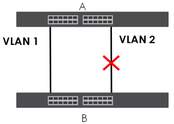
With MSTP, VLANs 1 and 2 are mapped to different spanning trees in the network. Therefore traffic from the two VLANs travel on different paths. The following figure shows the network example using MSTP.
MSTP Network Example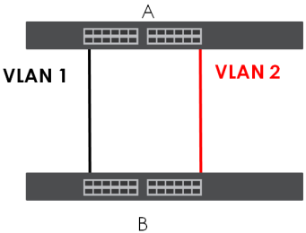
MST Region
An MST region is a logical grouping of multiple network devices that appears as a single device to the rest of the network. Each MSTP-enabled device can only belong to one MST region. When BPDUs enter an MST region, external path cost (of paths outside this region) is increased by one. Internal path cost (of paths within this region) is increased by one when BPDUs traverse the region.
Devices that belong to the same MST region are configured to have the same MSTP configuration identification settings. These include the following parameters:
• Name of the MST region
• Revision level as the unique number for the MST region
• VLAN-to-MST Instance mapping
MST Instance
An MST Instance (MSTI) is a spanning tree instance. VLANs can be configured to run on a specific MSTI. Each created MSTI is identified by a unique number (known as an MST ID) known internally to a region. Therefore an MSTI does not span across MST regions.
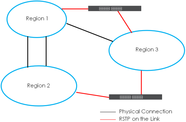
The following figure shows an example where there are two MST regions. Regions 1 and 2 have two spanning tree instances.
MSTIs in Different Regions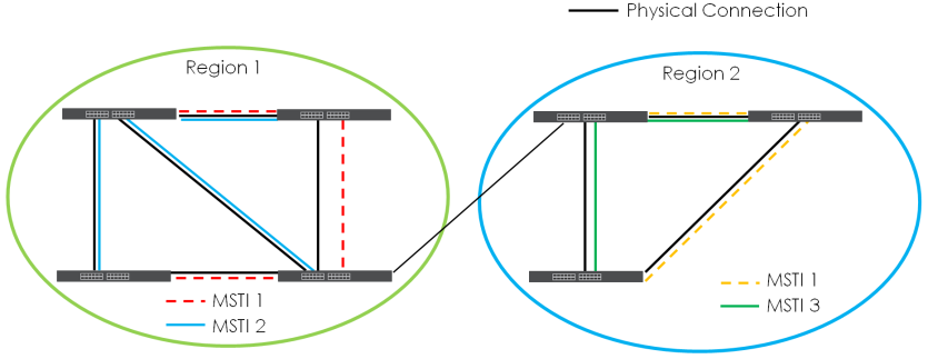
Common and Internal Spanning Tree (CIST)
A CIST represents the connectivity of the entire network and it is equivalent to a spanning tree in an STP/RSTP. The CIST is the default MST instance (MSTID 0). Any VLANs that are not members of an MST instance are members of the CIST. In an MSTP-enabled network, there is only one CIST that runs between MST regions and single spanning tree devices. A network may contain multiple MST regions and other network segments running RSTP.
MSTP and Legacy RSTP Network Example