Security Gateway
Overview
This chapter discusses the menus that you can use to monitor the Nebula managed Security Gateways in your network and configure settings even before a gateway is deployed and added to the site.
Nebula Device refers to Nebula NSG devices in this chapter. The Security gateway menus are shown for Nebula NSG devices only.
Monitor
Use the Monitor menus to check the Nebula Device information, client information, event log messages and summary report for the Nebula Device in the selected site.
Security Appliance
This screen allows you to view the detailed information about a Nebula Device in the selected site. Click Security gateway > Monitor > Security gateway to access this screen.
Security gateway > Monitor > Security gateway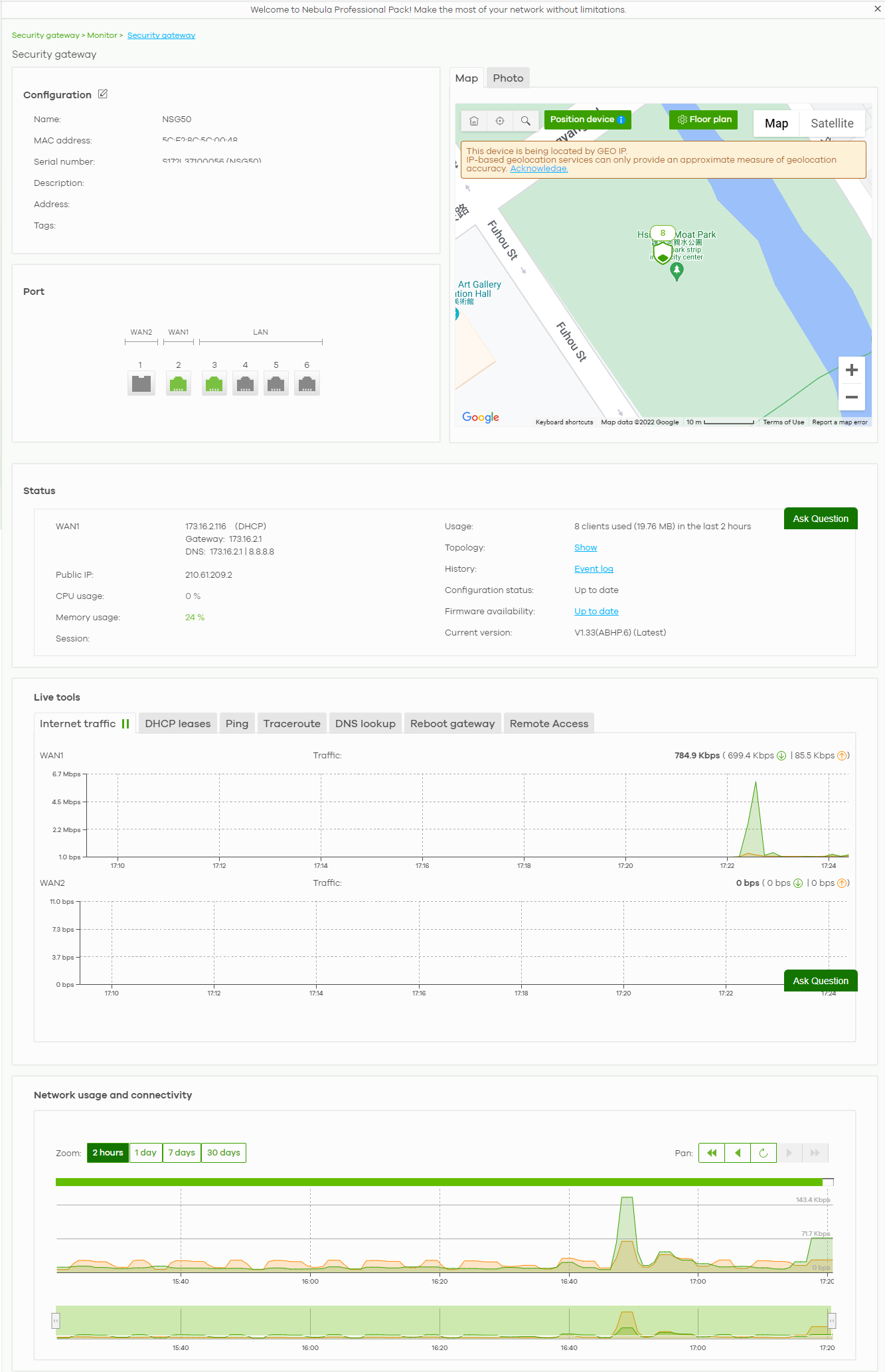
The following table describes the labels in this screen.
Label | Description |
|---|---|
Configuration Click the edit icon to change the Nebula Device name, description, tags and address. You can also move the Nebula Device to another site or remove. | |
Name | This shows the descriptive name of the Nebula Device. |
MAC address | This shows the MAC address of the Nebula Device. |
Serial number | This shows the serial number of the Nebula Device. |
Description | This shows the user-specified description for the Nebula Device. |
Address | This shows the user-specified address for the Nebula Device. |
Tags | This shows the user-specified tag for the Nebula Device. |
Port | This shows the ports on the Nebula Device. The port is highlighted in green color when it is connected and the link is up. Move the pointer over a port to see additional port information, such as its name, connection status, MAC address, and connection speed. |
Name | This shows the descriptive name of the port. |
Status | This shows the connection status of the port. |
MAC address | This shows the MAC address of the port. |
Speed | This shows the current connection speed of the port. If the speed is unavailable, this displays “Ethernet”. |
LLDP | This shows the LLDP information received on the port. |
Map | This shows the location of the Nebula Device on the Google map (Map view or Satellite imagery view) or on a floor plan. Click Floor plan to display a list of existing floor plans. Each floor plan has a drawing that shows the rooms scaled and viewed from above. Drag-and-drop your Nebula Device directly on the Google map or click Position device to update the Nebula Device’s address (physical location). • Select GEO IP to use the public IP address of the Nebula Device. • Select Get my location from web browser to use the public IP address of the computer accessing the NCC portal. • Select Use the following address or coordinates to enter the complete address or coordinates of the Nebula Device. |
Photo | This shows the photo of the Nebula Device. Click Add to upload one or more photos. Click x to remove a photo. |
Status | |
WAN1/WAN2 | This shows the IP address, gateway, DNS, and VLAN ID information for the active WAN connection. |
Public IP | This shows the global (WAN) IP address of the Nebula Device. |
CPU usage | This shows what percentage of the Nebula Device’s processing capability is currently being used. |
Memory usage | This shows what percentage of the Nebula Device’s RAM is currently being used. |
Security Service | This shows whether Nebula Security Services (NSS) are enabled on the Nebula Device. Click What is this? to view the type of enabled security services. When the gateway’s NSS license expires, NSS is automatically disabled. This field displays an edit button which you can use to re-enable the services after renewing the NSS license. |
Usage | This shows the amount of data that has been transmitted or received by the Nebula Device’s clients. |
Topology | |
History | Click Event log to go to the Security gateway > Monitor > Event log screen. |
Configuration status | This shows whether the configuration on the Nebula Device is up-to-date. |
Firmware availability | This shows whether the firmware installed on the Nebula Device is up-to-date. |
Current version | This shows the firmware version currently installed on the Nebula Device. |
Live tools | |
Internet traffic | This shows the WAN port statistics. The y-axis represents the transmission rate in Kbps (kilobits per second). The x-axis shows the time period over which the traffic flow occurred. |
DHCP leases | This shows the IP addresses currently assigned to DHCP clients. |
Ping | Enter the host name or IP address of a computer that you want to perform ping in order to test a connection and click Ping. You can select the interface through which the Nebula Device sends queries for ping. |
Traceroute | Enter the host name or IP address of a computer that you want to perform the traceroute function. This determines the path a packet takes to the specified computer. |
DNS lookup | Enter a host name and click Run to resolve the IP address for the specified domain name. |
Reboot gateway | Click the Reboot button to restart the Nebula Device. |
Remote Access | This option is available only for the Nebula Device owner. Establish a remote connection by specifying the Port number and clicking Establish. |
Network usage and connectivity Move the cursor over the chart to see the transmission rate at a specific time. | |
Zoom | Select to view the statistics in the past 2 hours, day, week, or month. |
Pan | Click to move backward or forward by one day or week. |
Clients
This menu item redirects to Site-Wide > Monitor > Clients, with type set to Security gateway clients. For details, see Clients.
Event Log
Use this screen to view Nebula Device log messages. You can enter a key word, select one or multiple event types, or specify a date/time or a time range to display only the log messages that match these criteria.
Select Range to set a time range or select Before to choose a specific date/time and the number of hours/minutes to display only the log messages generated within a certain period of time (before the specified date/time). Then click Search to update the list of logs based on the search criteria. The maximum allowable time range is 30 days.
Click Security gateway > Monitor > Event Log to access this screen.
Security gateway > Monitor > Event log
VPN Connections
Use this screen to view the status of site-to-site IPSec VPN connections and L2TP VPN connections.
Click Security gateway > Monitor > VPN Connections to access this screen.
Security gateway > Monitor > VPN Connections
The following table describes the labels in this screen.
Label | Description |
|---|---|
Click this button to reload the data-related frames on this page. | |
Connection Status | |
Configuration | This shows the number and address of the local networks behind the Nebula Device, on which the computers are allowed to use the VPN tunnel. |
NAT Type | This shows the public IP address or the domain name that is configured and mapped to the Nebula Device on the NAT router. |
Site Connectivity | |
Location | This shows the name of the site to which the peer gateway is assigned. Click the name to go to the Security gateway > Configure > Site-to-Site VPN screen, where you can modify the VPN settings. |
Subnet(s) | This shows the address of the local networks behind the Nebula Device. |
Status | This shows whether the VPN tunnel is connected or disconnected. |
Inbound (Bytes) | This shows the amount of traffic that has gone through the VPN tunnel from the remote IPSec router to the Nebula Device since the VPN tunnel was established. |
Outbound (Bytes) | This shows the amount of traffic that has gone through the VPN tunnel from the Nebula Device to the remote IPSec router since the VPN tunnel was established. |
Tunnel up time | This shows how many seconds the VPN tunnel has been active. |
Last heartbeat | This shows the last date and time a heartbeat packet is sent to determine if the VPN tunnel is up or down. |
Client to site VPN login account | |
User Name | This shows the remote user’s login account name. |
Hostname | This shows the name of the computer that has this L2TP VPN connection with the Nebula Device. |
Assigned IP | This shows the IP address that the Nebula Device assigned for the remote user’s computer to use within the L2TP VPN tunnel. |
Public IP | This shows the public IP address that the remote user is using to connect to the Internet. |
NSS Analysis Report
Use this screen to view the statistics report for NSS (Nebula Security Service), such as content filtering, Intrusion Detection and Prevention (IDP), application patrol, and anti-virus. The screen varies depending on the service type (Application, Content Filtering, or Anti-Virus) you select.
Click Security gateway > Monitor > NSS Analysis Report to access this screen.
Security gateway > Monitor > NSS Analysis Report
The following table describes the labels in this screen.
Label | Description |
|---|---|
Security Appliance – NSS Analysis | Select to view the report for the past day, week or month. Alternatively, select Custom range... to specify a time period the report will span. You can also select the number of results you want to view in a table. |
Select the type of service for which you want to view the statistics report. | |
Email report | Click this button to send summary reports by email, change the logo and set email schedules. |
Application The following fields displays when you select to view the application statistics. Click an application name to view information about the clients who use that application. Click Top Application under the chart to switch back to the previous screen. | |
y-axis | The y-axis shows the amount of the application’s traffic which has been transmitted or received. |
x-axis | The x-axis shows the time period over which the traffic flow occurred. |
Application | This shows the name of the application. Click an application name to view the IPv4 addresses of the clients who used the application. |
Description | This shows the name of the client who used the application. This field is available when you click the application name. Click the name to display the individual client statistics. See Event Log. |
IPv4 Address | This shows the IPv4 address of the client who used the application. This field is available when you click the application name. |
MAC Address | This shows the MAC address of the client who used the application. This field is available when you click the application name. |
Category | This shows the name of the category to which the application belongs. |
Usage | This shows the total amount of data consumed by the application used by all or a specific IPv4 address. |
% Usage | This shows the percentage of usage for the application used by all or a specific IPv4 address. |
Content Filtering The following fields display when you select to view the content filtering statistics. Click a website URL to view information about the clients who tried to access that web page. Click Content Filtering under the chart to switch back to the previous screen. | |
y-axis | The y-axis shows the number of hits on web pages that the Nebula Device’s content filter service has blocked. |
x-axis | The x-axis shows the time period over which the web page is checked. |
Website | This shows the URL of the web page to which the Nebula Device blocked access. Click a website URL to view the IPv4 addresses of the clients who tried to access the web page. |
Description | This shows the name of the client who tried to access the web page. This field is available when you click the website URL. Click the name to display the individual client statistics. See Event Log. |
IPv4 Address | This shows the IPv4 address of the client who tried to access the web page. This field is available when you click the website URL. |
MAC Address | This shows the MAC address of the client who tried to access the web page. This field is available when you click the website URL. |
Category | This shows the name of the category to which the web page belongs. |
Hits | This shows the number of hits on the web page visited by all or a specific IPv4 address. |
% Hits | This shows the percentage of the hit counts for the web page visited by all or a specific IPv4 address. |
Anti-Virus The following fields are displayed when you select Anti-Virus. Click a virus name to view information about the clients who sent the virus. Click the number in the center of the donut chart or Anti-Virus under the chart to switch back to the previous screen. | |
y-axis | The y-axis shows the total number of viruses that the gateway has detected. |
x-axis | The x-axis shows the time period over which the virus is detected. |
Virus Name | This shows the name of the virus that the Nebula Device has detected and blocked. Click a virus name to view the IPv4 addresses of the clients who sent the virus. |
Description | This shows the name of the client who sent the virus. This field is available when you click the virus name. Click the name to display the individual client statistics. See Event Log. |
IPv4 Address | This shows the IPv4 address of the virus sender. This field is available when you click the virus name. |
MAC Address | This shows the MAC address of the virus sender. This field is available when you click the virus name. |
Hits | This shows how many times the gateway has detected the virus sent by all or a specific IPv4 address. |
% Hits | This shows the percentage of the hit counts for the virus sent by all or a specific IPv4 address. |
Intrusion Detection / Prevention The following fields are displayed when you select Intrusion Detection / Prevention. The donut chart shows the number of potential network attacks detected by the Intrusion Detection and Prevention (IDP) service, if any. The number in the center of the donut chart indicates the number of network attacks blocked by the IDP service. | |
Signature Name | The name of the IDP signature that triggered the hit. The signature name identifies the type of intrusion pattern |
Hits | This shows the total number of network attacks blocked by the IDP service. |
% Hits | This shows the number of network attacks blocked as a percentage of the total number of network requests scanned by the IDP service. |
Summary Report
This screen displays network statistics for the Nebula Device of the selected site, such as WAN usage, top applications and/or top clients.
Click Security gateway > Monitor > Summary Report to access this screen.
Security gateway > Monitor > Summary Report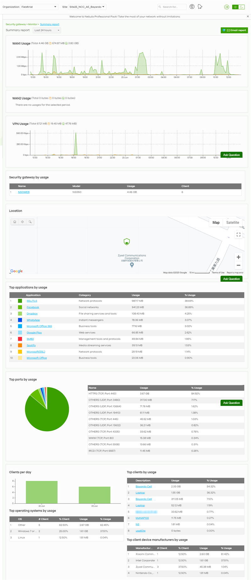
The following table describes the labels in this screen.
Label | Description |
|---|---|
Security gateway – Summary report | Select to view the report for the past day, week or month. Alternatively, select Custom range... to specify a time period the report will span. You can also select the number of results you want to view in a table. |
Email report | Click this button to send summary reports by email, change the logo and set email schedules. |
WAN1/WAN2 usage | |
y-axis | The y-axis shows the transmission speed of data sent or received through the WAN connection in kilobits per second (Kbps). |
x-axis | The x-axis shows the time period over which the traffic flow occurred. |
VPN usage | |
y-axis | The y-axis shows the transmission speed of data sent or received through the VPN tunnel in kilobits per second (Kbps). |
x-axis | The x-axis shows the time period over which the traffic flow occurred. |
Security gateway by usage | |
This shows the index number of the Nebula Device. | |
Name | This shows the descriptive name of the Nebula Device. |
Model | This shows the model number of the Nebula Device. |
Usage | This shows the amount of data that has been transmitted through the Nebula Device’s WAN port. |
Client | This shows the number of clients currently connected to the Nebula Device. |
Location This shows the location of the Nebula Devices on the map. | |
Top applications by usage | |
This shows the index number of the application. | |
Application | This shows the application name. |
Category | This shows the name of the category to which the application belongs. |
Usage | This shows the amount of data consumed by the application. |
% Usage | This shows the percentage of usage for the application. |
Top ports by usage | This shows the top ten applications/services and the ports that identify a service. |
Name | This shows the service name and the associated port numbers. |
Usage | This shows the amount of data consumed by the service. |
% Usage | This shows the percentage of usage for the service. |
Clients per day | |
y-axis | The y-axis represents the number of clients. |
x-axis | The x-axis represents the date. |
Top operating systems by usage | |
This shows the index number of the operating system. | |
OS | This shows the operating system of the client device. |
# Client | This shows how many client devices use this operating system. |
% Client | This shows the percentage of top client devices which use this operating system. |
# Usage | This shows the amount of data consumed by the client device on which this operating system is running. |
% Usage | This shows the percentage of usage for top client devices which use this operating system. |
Top clients by usage | |
This shows the index number of the client. | |
Description | This shows the descriptive name or MAC address of the client. |
Usage | This shows the total amount of data transmitted and received by the client. |
% Usage | This shows the percentage of usage for the client. |
Top client device manufacturers by usage | |
This shows the index number of the client device. | |
Manufacturer | This shows the manufacturer name of the client device. |
Client | This shows how many client devices are made by the manufacturer. |
% Client | This shows the percentage of top client devices which are made by the manufacturer. |
Usage | This shows the total amount of data transmitted and received by the client device. |
% Usage | This shows the percentage of usage for the client device. |
Configure
Use the Configure menus to configure interface addressing, firewall, site-to-site VPN, captive portal, traffic shaping, authentication server and other Nebula Device settings for the Nebula Device of the selected site.
Interface Addressing
Use this screen to configure network mode, port grouping, interface address, static route and DDNS settings on the Nebula Device. To access this screen, click Security gateway > Configure > Interface addressing.
Security gateway > Configure > Interface addressing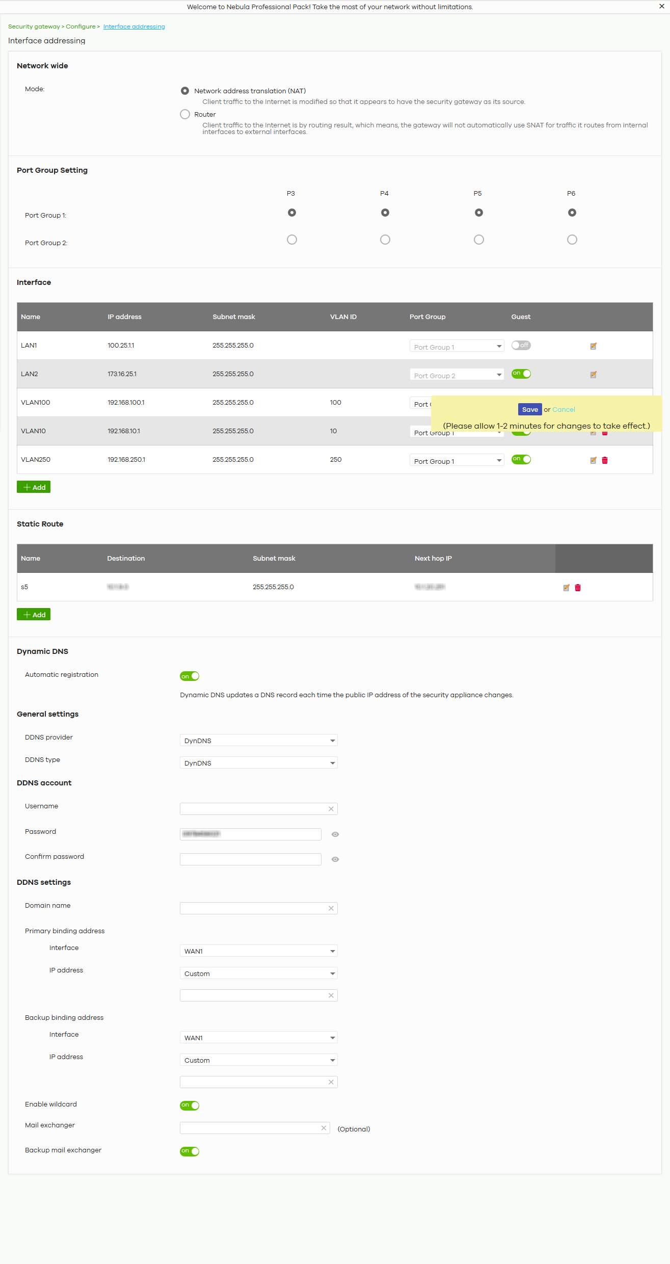
The following table describes the labels in this screen.
Label | Description |
|---|---|
Network wide | |
Mode | Select Network address translation (NAT) to have the Nebula Device automatically use SNAT for traffic it routes from internal interfaces to external interfaces. Select Router to have the Nebula Device forward packets according to the routing policies. The Nebula Device does not automatically convert a packet’s source IP address. |
Port Group Setting | Port groups create a hardware connection between physical ports at the layer-2 (data link, MAC address) level. The physical LAN Ethernet ports are shown at the top (P3, P4, and so on) and the port groups are shown at the left of the screen. Use the radio buttons to select which ports are in each port group. For example, select a port’s Port Group 1 radio button to use the port as part of the first port group. The port will use the first group’s IP address. |
Interface By default, LAN1 is created on top of port group 1 and LAN2 is on top of port group 2. | |
Name | This shows the name of the interface (network) on the Nebula Device. |
IP address | This shows the IP address of the interface (network). |
Subnet mask | This shows the subnet mask of the interface (network). |
VLAN ID | This shows the ID number of the VLAN with which the interface (network) is associated. If you have associated an SSID with the VLAN ID, the Smart VLAN screen displays after you change or delete the VLAN ID and click Save. You can exit the screen without saving, or apply your changes directly. If the Smart guest/VLAN network feature is enabled in the Site-Wide > Configure > General settings screen, you can select to apply the changes and update the SSID’s VLAN setting as well.  |
Port group | This shows the name of the port group to which the interface (network) belongs. |
Guest | Select On to configure the interface as a Guest interface. Devices connected to a Guest interface will have Internet access but cannot communicate with each other directly or access network sources behind the Nebula Device. Otherwise, select Off to not use the interface as a Guest interface. |
 | Click this button to modify the network settings. See Local LAN (Add VLAN) for detailed information. |
 | Click this icon to remove a VLAN entry. |
Add | Click this button to create a VLAN, which is then associated with one Ethernet interface (network). See Local LAN (Add VLAN) for detailed information. |
Static Route | |
Name | This shows the name of the static route. |
Destination | This shows the destination IP address. |
Subnet mask | This shows the IP subnet mask. |
Next hop IP | This shows the IP address of the next-hop gateway or the interface through which the traffic is routed. The gateway is a router or switch on the same segment as your Nebula Device's interfaces. It helps forward packets to their destinations. |
| Click this button to modify the static route settings. See Static Route for detailed information. |
| Click this icon to remove a static route. |
Add | Click this button to create a new static route. See Static Route for detailed information. |
Dynamic DNS | |
Automatic registration | Click On to use dynamic DNS. Otherwise, select Off to disable it. |
General Settings | |
DDNS provider | Select your Dynamic DNS service provider from the drop-down list box. If you select User custom, create your own DDNS service. |
DDNS type | Select the type of DDNS service you are using. Select User custom to create your own DDNS service and configure the DYNDNS Server, URL, and Additional DDNS Options fields below. |
DDNS account | |
Username | Enter the user name used when you registered your domain name. |
Password | Enter the password provided by the DDNS provider. |
Confirm password | Enter the password again to confirm it. |
DDNS settings | |
Domain name | Enter the domain name you registered. |
Primary binding address | Use these fields to set how the Nebula Device determines the IP address that is mapped to your domain name in the DDNS server. The Nebula Device uses the Backup binding address if the interface specified by these settings is not available. |
Interface | Select the interface to use for updating the IP address mapped to the domain name. |
IP address | Select Auto if the interface has a dynamic IP address. The DDNS server checks the source IP address of the packets from the Nebula Device for the IP address to use for the domain name. You may want to use this if there are one or more NAT routers between the Nebula Device and the DDNS server. Select Custom if you have a static IP address. Enter the IP address to use it for the domain name. Select Interface to have the Nebula Device use the IP address of the specified interface. |
Backup binding address | Use these fields to set an alternate interface to map the domain name to when the interface specified by the Primary binding address settings is not available. |
Interface | Select the interface to use for updating the IP address mapped to the domain name. |
IP address | Select Auto if the interface has a dynamic IP address. The DDNS server checks the source IP address of the packets from the Nebula Device for the IP address to use for the domain name. You may want to use this if there are one or more NAT routers between the Nebula Device and the DDNS server. Select Custom if you have a static IP address. Enter the IP address to use it for the domain name. Select Interface to have the Nebula Device use the IP address of the specified interface. |
Enable wildcard | This option is only available with a DynDNS account. Enable the wildcard feature to alias sub-domains to be aliased to the same IP address as your (dynamic) domain name. This feature is useful if you want to be able to use, for example, www.yourhost.dyndns.org and still reach your hostname. |
Mail exchanger | This option is only available with a DynDNS account. DynDNS can route email for your domain name to a mail server (called a mail exchanger). For example, DynDNS routes email for john-doe@yourhost.dyndns.org to the host record specified as the mail exchanger. If you are using this service, type the host record of your mail server here. Otherwise, leave the field blank. |
Backup mail exchanger | This option is only available with a DynDNS account. Select this check box if you are using DynDNS’s backup service for email. With this service, DynDNS holds onto your email if your mail server is not available. Once your mail server is available again, the DynDNS server delivers the mail to you. See www.dyndns.org for more information about this service. |
DYNDNS Server | This field displays when you select User custom from the DDNS provider field above. Enter the IP address of the server that will host the DDNS service. |
URL | This field displays when you select User custom from the DDNS provider field above. Enter the URL that can be used to access the server that will host the DDNS service. |
Additional DDNS Options | This field displays when you select User custom from the DDNS provider field above. These are the options supported at the time of writing: • dyndns_system to specify the DYNDNS Server type – for example, dyndns@dyndns.org • ip_server_name which should be the URL to get the server’s public IP address – for example, http://myip.easylife.tw/ |
Local LAN (Add VLAN)
Click the Add button or click the Edit button in the Interface section of the Security gateway > Configure > Interface addressing screen.
Security gateway > Configure > Interface addressing: Local LAN (VLAN)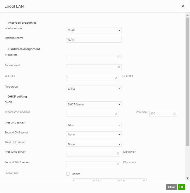
The following table describes the labels in this screen.
Label | Description |
|---|---|
Interface properties | |
Interface type | Select VLAN to add a virtual interface. |
Interface name | This field is read-only if you are editing an existing interface. Specify a name for the interface. The format of interface names is strict. Each name consists of 2 – 4 letters (interface type), followed by a number (x). For most interfaces, x is limited by the maximum number of the type of interface. For VLAN interfaces, x is defined by the number you enter in the VLAN name field. For example, VLAN interfaces are vlan0, vlan1, vlan2, and so on. |
IP address assignment | |
IP address | Enter the IP address for this interface. |
Subnet mask | Enter the subnet mask of this interface in dot decimal notation. The subnet mask indicates what part of the IP address is the same for all computers in the network. |
VLAN ID | Enter the VLAN ID. This 12-bit number uniquely identifies each VLAN. Allowed values are 1 – 4094. (0 and 4095 are reserved.) |
Port group | Select the name of the port group to which you want the interface to (network) belong. |
DHCP setting | |
DHCP | Select what type of DHCP service the Nebula Device provides to the network. Choices are: None – the Nebula Device does not provide any DHCP service. There is already a DHCP server on the network. DHCP Relay – the Nebula Device routes DHCP requests to one or more DHCP servers you specify. The DHCP servers may be on another network. DHCP Server – the Nebula Device assigns IP addresses and provides subnet mask, gateway, and DNS server information to the network. The Nebula Device is the DHCP server for the network. |
These fields appear if the Nebula Device is a DHCP Relay. | |
Relay server 1 | Enter the IP address of a DHCP server for the network. |
Relay server 2 | This field is optional. Enter the IP address of another DHCP server for the network. |
These fields appear if the Nebula Device is a DHCP Server. | |
IP pool start address | Enter the IP address from which the Nebula Device begins allocating IP addresses. If you want to assign a static IP address to a specific computer, click Add new under Static DHCP Table. |
Pool size | Enter the number of IP addresses to allocate. This number must be at least one and is limited by the interface’s Subnet mask. For example, if the Subnet mask is 255.255.255.0 and IP pool start address is 10.10.10.10, the Nebula Device can allocate 10.10.10.10 to 10.10.10.254, or 245 IP addresses. |
First DNS server Second DNS server Third DNS server | Specify the IP addresses up to three DNS servers for the DHCP clients to use. Use one of the following ways to specify these IP addresses. Custom Defined – enter a static IP address. From ISP – select the DNS server that another interface received from its DHCP server. NSG – the DHCP clients use the IP address of this interface and the Nebula Device works as a DNS relay. |
First WINS server Second WINS server | Type the IP address of the WINS (Windows Internet Naming Service) server that you want to send to the DHCP clients. The WINS server keeps a mapping table of the computer names on your network and the IP addresses that they are currently using. |
Lease time | Specify how long each computer can use the information (especially the IP address) before it has to request the information again. Choices are: infinite – select this if IP addresses never expire. days, hours, minutes – select this to enter how long IP addresses are valid. |
Extended options | This table is available if you selected DHCP server. Configure this table if you want to send more information to DHCP clients through DHCP packets. Click Add new to create an entry in this table. See DHCP Option for detailed information. |
Name | This is the option’s name. |
Code | This is the option’s code number. |
Type | This is the option’s type. |
Value | This is the option’s value. |
Click the edit icon to modify it. Click the remove icon to delete it. | |
Static DHCP Table | Configure a list of static IP addresses the Nebula Device assigns to computers connected to the interface. Otherwise, the Nebula Device assigns an IP address dynamically using the interface’s IP pool start address and Pool size. Click Add new to create an entry in this table. |
IP address | Enter the IP address to assign to a device with this entry’s MAC address. |
MAC | Enter the MAC address to which to assign this entry’s IP address. |
Description | Enter a description to help identify this static DHCP entry. |
Close | Click Close to exit this screen without saving. |
OK | Click OK to save your changes. |
Link Aggregation Groups
A Link Aggregation Group (LAG) combines multiple Ethernet ports into a single logical interface, in order to increase network bandwidth and/or availability.
Ports in the group can all connect to a target simultaneously, combining their bandwidth. A LAG can also offer higher network availability; if any port in the group becomes disconnected, the LAG can continue sending data using another port.
Interface Addressing with Link Aggregation Groups
If the Nebula Device of the selected site supports Link Aggregation Groups (LAGs), for example NSG300, you can create a LAG by clicking Add.
After you create a LAG, the Port Group Settings and Interface sections of the Interface Addressing screen change. The new screen layout allows you to view and configure which ports are in a LAG.
Security gateway > Configure > Interface addressing (LAG Interface Type)
The following table describes the labels in this screen.
Label | Description |
|---|---|
Port Group Setting | Select which port group or Link Aggregation Group (LAG) an Ethernet port belongs to. When LAGs are enabled, NCC adds each available LAN Ethernet port (port 3 and higher) to a separate port group, named LAN1, LAN2, LAN3, and so on. These default port groups cannot be modified or renamed. |
Interface | |
Name | This shows the name of the interface (network) on the Nebula Device. |
IP address | This shows the IP address of the interface (network). |
Subnet mask | This shows the subnet mask of the interface (network). |
VLAN ID | This shows the ID number of the VLAN with which the interface (network) is associated. |
Port group | For an Ethernet port, this shows the name of the port group to which the port belongs. For a link aggregation group, this shows its member port groups. |
Guest | Select On to configure the interface as a Guest interface. Devices connected to a Guest interface will have Internet access but cannot communicate with each other directly or access network sources behind the Nebula Device. Otherwise, select Off to not use the interface as a Guest interface. |
| Click this button to modify the network settings. See Local LAN (Add VLAN) for detailed information. If the interface is a member of a link aggregation group, you cannot edit the interface’s network settings. |
| Click this icon to delete a VLAN entry or link aggregation group. |
Add | Click this button to create a VLAN or link aggregation group. • For details on creating a VLAN, see Local LAN (Add VLAN). • For details on creating a link aggregation group, see Local LAN (LAG Interface Type). |
Local LAN (LAG Interface Type)
Click the Add button or click the Edit button in the Interface section of the Security gateway > Configure > Interface addressing screen.
Security gateway > Configure > Interface addressing: Local LAN (LAG Interface Type)
The following table describes the labels in this screen.
Label | Description |
|---|---|
Interface properties | |
Interface type | Select LAG to add a link aggregation group. |
Interface name | Specify a name for the interface. This must be “LAG” plus a number, for example “LAG1”. |
LAG Configuration | |
Mode | Select a mode for this Link Aggregation Group (LAG) interface. Choices are as follows: • active-backup: Only one port in the LAG interface is active and another port becomes active only if the active port fails. • 802.3ad (IEEE 802.3ad Dynamic link aggregation): Link Aggregation Control Protocol (LACP) negotiates automatic combining of ports and balances the traffic load across the LAG link by sending LACP packets to the directly connected device that also implements LACP. The ports must have the same speed and duplex settings. • balance-alb (adaptive load balancing): Traffic is distributed according to the current load on each port by ARP negotiation. Incoming traffic is received by the current port. If the receiving port fails, another port takes over the MAC address of the failed receiving port. |
Link Monitoring | Select how each link is monitored. mii (Media Independent Interface) – The Nebula Device monitors the state of the local interface only. The Nebula Device cannot tell if the link can transmit or receive packets. arp – The Nebula Device monitors the link by sending ARP queries. The Nebula Device then uses the reply to know if the link is up and that traffic is flowing through the link. |
Miimom | This field displays for mii Link Monitoring. Set the interval in milliseconds that the system polls the Media Independent Interface (MII) to get the link’s status. |
Updelay | This field displays for mii Link Monitoring. Set the waiting time in milliseconds to confirm that a member interface link is up. |
Downdelay | This field displays for mii Link Monitoring. Set the waiting time in milliseconds to confirm that a member interface link is down. |
IP address assignment | |
IP address | Enter the IP address for this interface. |
Subnet mask | Enter the subnet mask of this interface in dot decimal notation. The subnet mask indicates what part of the IP address is the same for all computers in the network. |
VLAN ID | Enter the VLAN ID. This 12-bit number uniquely identifies each VLAN. Allowed values are 1 – 4094. (0 and 4095 are reserved.) |
Port group | Select the name of the port group to which you want the interface to (network) belong. |
DHCP setting | |
DHCP | Select what type of DHCP service the Nebula Device provides to the network. Choices are: None – the Nebula Device does not provide any DHCP services. There is already a DHCP server on the network. DHCP Relay – the Nebula Device routes DHCP requests to one or more DHCP servers you specify. The DHCP servers may be on another network. DHCP Server – the Nebula Device assigns IP addresses and provides subnet mask, gateway, and DNS server information to the network. The Nebula Device is the DHCP server for the network. |
These fields appear if the Nebula Device is a DHCP Relay. | |
Relay server 1 | Enter the IP address of a DHCP server for the network. |
Relay server 2 | This field is optional. Enter the IP address of another DHCP server for the network. |
These fields appear if the Nebula Device is a DHCP Server. | |
IP pool start address | Enter the IP address from which the Nebula Device begins allocating IP addresses. If you want to assign a static IP address to a specific computer, click Add new under Static DHCP Table. |
Pool size | Enter the number of IP addresses to allocate. This number must be at least one and is limited by the interface’s Subnet mask. For example, if the Subnet mask is 255.255.255.0 and IP pool start address is 10.10.10.10, the Nebula Device can allocate 10.10.10.10 to 10.10.10.254, or 245 IP addresses. |
First DNS server Second DNS server Third DNS server | Specify the IP addresses of up to three DNS servers for the DHCP clients to use. Use one of the following ways to specify these IP addresses. Custom Defined – enter a static IP address. From ISP – select the DNS server that another interface received from its DHCP server. NSG – the DHCP clients use the IP address of this interface and the Nebula Device works as a DNS relay. |
First WINS server Second WINS server | Enter the IP address of the WINS (Windows Internet Naming Service) server that you want to send to the DHCP clients. The WINS server keeps a mapping table of the computer names on your network and the IP addresses that they are currently using. |
Lease time | Specify how long each computer can use the information (especially the IP address) before it has to request the information again. Choices are: infinite – select this if IP addresses never expire days, hours, minutes – select this to enter how long IP addresses are valid. |
Extended options | This table is available if you selected DHCP server. Configure this table if you want to send more information to DHCP clients through DHCP packets. Click Add new to create an entry in this table. See DHCP Option for detailed information. |
Name | This is the option’s name. |
Code | This is the option’s code number. |
Type | This is the option’s type. |
Value | This is the option’s value. |
Click the edit icon to modify it. Click the remove icon to delete it. | |
Static DHCP Table | Configure a list of static IP addresses the Nebula Device assigns to computers connected to the interface. Otherwise, the Nebula Device assigns an IP address dynamically using the interface’s IP pool start address and Pool size. Click Add new to create an entry in this table. |
IP address | Enter the IP address to assign to a device with this entry’s MAC address. |
MAC | Enter the MAC address to which to assign this entry’s IP address. |
Description | Enter a description to help identify this static DHCP entry. |
Close | Click Close to exit this screen without saving. |
OK | Click OK to save your changes. |
DHCP Option
Click the Add new button under Extended options in the Security gateway > Configure > Interfaces addressing: Local LAN screen.
Security gateway > Configure > Interfaces addressing: Local LAN: DHCP Option
The following table describes the labels in this screen.
Label | Description |
|---|---|
Option | Select which DHCP option that you want to add in the DHCP packets sent through the interface. |
Name | This field displays the name of the selected DHCP option. If you selected User_Defined in the Option field, enter a descriptive name to identify the DHCP option. |
Code | This field displays the code number of the selected DHCP option. If you selected User_Defined in the Option field, enter a number for the option. This field is mandatory. |
Type | This is the type of the selected DHCP option. If you selected User_Defined in the Option field, select an appropriate type for the value that you will enter in the next field. Misconfiguration could result in interface lockout. |
Value | Enter the value for the selected DHCP option. For example, if you selected TFTP Server Name (66) and the type is TEXT, enter the DNS domain name of a TFTP server here. This field is mandatory. |
First IP address Second IP address Third IP address | If you selected Time Server (4), NTP Server (41), SIP Server (120), CAPWAP AC (138), or TFTP Server (150), you have to enter at least one IP address of the corresponding servers in these fields. The servers should be listed in order of your preference. |
First enterprise ID Second enterprise ID | If you selected VIVC (124) or VIVS (125), you have to enter at least one vendor’s 32-bit enterprise number in these fields. An enterprise number is a unique number that identifies a company. |
First class Second class | If you selected VIVC (124), enter the details of the hardware configuration of the host on which the client is running, or of industry consortium compliance. |
First information Second information | If you selected VIVS (125), enter additional information for the corresponding enterprise number in these fields. |
First FQDN Second FQDN Third FQDN | If the Type is FQDN, you have to enter at least one domain name of the corresponding servers in these fields. The servers should be listed in order of your preference. |
Close | Click Close to exit this screen without saving. |
OK | Click OK to save your changes. |
Static Route
Click the Add button in the Static Route section of the Security gateway > Configure > Interfaces addressing screen.
Security gateway > Configure > Interfaces addressing: Static Route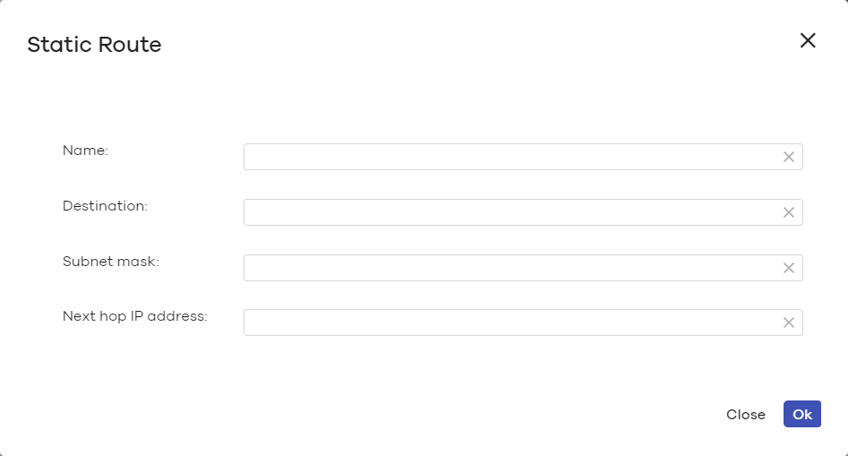
The following table describes the labels in this screen.
Label | Description |
|---|---|
Name | Enter a descriptive name for this route. |
Destination | Specifies the IP network address of the final destination. Routing is always based on network number. |
Subnet mask | Enter the IP subnet mask. |
Next hop IP address | Enter the IP address of the next-hop gateway. |
Close | Click Close to exit this screen without saving. |
OK | Click OK to save your changes. |
Policy Route
Use policy routes and static routes to override the Nebula Device’s default routing behavior in order to send packets through the appropriate next-hop gateway, interface or VPN tunnel.
A policy route defines the matching criteria and the action to take when a packet meets the criteria. The action is taken only when all the criteria are met. Use this screen to configure policy routes.
Click Security gateway > Configure > Policy Route to access this screen.
Security gateway > Configure > Policy Route
The following table describes the labels in this screen.
Label | Description |
|---|---|
 | Click the icon of a rule and drag the rule up or down to change the order. |
Enabled | Select the check box to turn on the rule. Otherwise, clear the check box to turn off the rule. |
Type | This shows whether the packets will be routed to a different gateway (INTRANET), VPN tunnel (VPN) or outgoing interface (INTERNET). |
Protocol | This displays the IP protocol that defines the service used by the packets. Any means all services. |
Source IP | This is the source IP addresses from which the packets are sent. |
Source Port | This displays the port that the source IP addresses are using in this policy route rule. The gateway applies the policy route to the packets sent from the corresponding service port. Any means all service ports. |
Destination IP | This is the destination IP addresses to which the packets are transmitted. |
Destination Port | This displays the port that the destination IP addresses are using in this policy route rule. Any means all service ports. |
Next-Hop | This is the next hop to which packets are directed. It helps forward packets to their destinations and can be a router, VPN tunnel or outgoing interface. |
| Click this icon to change the profile settings. |
| Click this icon to remove the profile. |
Add | Click this button to create a new policy route. See Add application patrol profile for more information. |
Add/Edit policy route
Click the Add button or an edit icon in the Security gateway > Configure > Policy Route screen to access this screen.
Security gateway > Configure > Policy Route: Add/Edit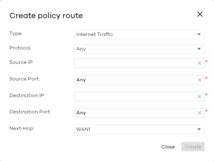
The following table describes the labels in this screen.
Label | Description |
|---|---|
Type | Select Internet Traffic to route the matched packets through the specified outgoing interface to a gateway (which is connected to the interface). Select Intranet Traffic to route the matched packets to the next-hop router or switch you specified in the Next-Hop field. Select VPN Traffic to route the matched packets through the VPN tunnel you specified in the Next-Hop field. |
Protocol | Select TCP or UDP if you want to specify a protocol for the policy route. Otherwise, select Any. |
Source IP | Enter a source IP address from which the packets are sent. |
Source Port | Enter the port number (1 – 65535) from which the packets are sent. The Nebula Device applies the policy route to the packets sent from the corresponding service port. Any means all service ports. |
Destination IP | Enter a destination IP address to which the packets go. |
Destination Port | Enter the port number (1 – 65535) to which the packets go. The Nebula Device applies the policy route to the packets that go to the corresponding service port. Any means all service ports. |
Next-Hop | If you select Internet Traffic in the Type field, select the WAN interface to route the matched packets through the specified outgoing interface to a Nebula Device connected to the interface. If you select Intranet Traffic in the Type field, enter the IP address of the next-hop router or switch. If you select VPN Traffic in the Type field, select the remote VPN gateway’s site name. |
Close | Click this button to exit this screen without saving. |
Create | Click this button to save your changes and close the screen. |
Firewall
By default, a LAN user can initiate a session from within the LAN and the Nebula Device allows the response. However, the Nebula Device blocks incoming traffic initiated from the WAN and destined for the LAN. Use this screen to configure firewall rules for outbound traffic, application patrol, schedule profiles and port forwarding rules for inbound traffic.
Click Security gateway > Configure > Firewall to access this screen.
Security gateway > Configure > Firewall
The following table describes the labels in this screen.
Label | Description |
|---|---|
Security Policy | |
Policy rules | |
| Click the icon of a rule and drag the rule up or down to change the order. |
Enabled | Select the check box to turn on the rule. Otherwise, clear the check box to turn off the rule. |
Policy | Select what the Nebula Device is to do with packets that match this rule. Select Deny to silently discard the packets without sending a TCP reset packet or an ICMP destination-unreachable message to the sender. Select Allow to permit the passage of the packets. Select a pre-defined application patrol profile to have the Nebula Device take the action set in the profile when traffic matches the application patrol signatures. See Add application patrol profile for how to create an application patrol profile. |
Protocol | Select the IP protocol to which this rule applies. Choices are: TCP, UDP, and Any. |
Source | Specify the source IP addresses to which this rule applies. You can specify multiple IP addresses or subnets in the field separated by a comma (","). Enter any to apply the rule to all IP addresses. |
Destination | Specify the destination IP addresses or subnet to which this rule applies. You can specify multiple IP addresses or subnets in the field separated by a comma (","). Enter any to apply the rule to all IP addresses. |
Dst Port | Specify the destination ports to which this rule applies. You can specify multiple ports separated by a comma (","). Enter any to apply the rule to all ports. |
Schedule | Select the name of the schedule profile that the rule uses. Always means the rule is active at all times if enabled. |
Description | Enter a descriptive name of up to 60 printable ASCII characters for the rule. |
| Click this icon to remove the rule. |
Add | Click this button to create a new rule. |
Security gateway services | |
Service | This shows the name of the service. |
Allowed remote IPs | Specify the IP address or a range of IP addresses (CIDR) with which the computer is allowed to access the Nebula Device using the service. Any allows all IP addresses. |
Application Patrol | |
Application monitor | Click On to enable traffic analysis for all applications and display information about the top 10 applications in the Site-wide > Monitor > Dashboard: Traffic Summary screen. Otherwise, select Off to disable traffic analysis for applications. |
Application profiles | |
Name | This shows the name of the application patrol profile. |
Description | This shows the description of the application patrol profile. |
| Click this icon to change the profile settings. |
| Click this icon to remove the profile. |
Add | Click this button to create a new application patrol profile. See Add application patrol profile for more information. |
Schedule profiles | |
This shows the name of the schedule profile and the number of the outbound rules that are using this schedule profile. | |
| Click this icon to change the profile settings. |
| Click this icon to remove the profile. |
Add | Click this button to create a new schedule profile. See Create new schedule for more information. |
SIP ALG | |
SIP ALG | Session Initiation Protocol (SIP) is an application-layer protocol that can be used to create voice and multimedia sessions over the Internet. Application Layer Gateway (ALG) allows the following applications to operate properly through the Nebula Device’s NAT. Turn on the SIP ALG to detect SIP traffic and help build SIP sessions through the Nebula Device’s NAT. Enabling the SIP ALG also allows you to use the application patrol to detect SIP traffic and manage the SIP traffic’s bandwidth. |
SIP Signaling Port | If you are using a custom UDP port number (not 5060) for SIP traffic, enter it here. |
ADVANCED OPTIONS | |
SIP Inactivity Timeout | Select this option to have the Nebula Device apply SIP media and signaling inactivity time out limits. |
SIP Media Inactivity Timeout | Use this field to set how many seconds (1 – 86400) the Nebula Device will allow a SIP session to remain idle (without voice traffic) before dropping it. If no voice packets go through the SIP ALG before the timeout period expires, the Nebula Device deletes the audio session. You cannot hear anything and you will need to make a new call to continue your conversation. |
SIP Signaling Inactivity Timeout | Most SIP clients have an “expire” mechanism indicating the lifetime of signaling sessions. The SIP user agent sends registration packets to the SIP server periodically and keeps the session alive in the Nebula Device. If the SIP client does not have this mechanism and makes no calls during the Nebula Device SIP timeout, the Nebula Device deletes the signaling session after the timeout period. Enter the SIP signaling session timeout value (1 – 86400). |
NAT | |
1:1 NAT A 1:1 NAT rule maps a public IP address to the private IP address of a LAN server to give WAN users access. If a private network server will initiate sessions to the outside clients, 1:1 NAT lets the Nebula Device translate the source IP address of the server’s outgoing traffic to the same public IP address that the outside clients use to access the server. | |
| Click the icon of a rule and drag the rule up or down to change the order. |
Enabled | Select the check box to turn on the rule. Otherwise, clear the check box to turn off the rule. |
Uplink | Select the interface of the Nebula Device on which packets for the NAT rule must be received. |
Public IP | Enter the destination IP address of the packets received by the interface specified in this NAT rule. |
LAN IP | Specify to which translated destination IP address this NAT rule forwards packets. |
Allowed Remote IP | Specify the remote IP address with which the computer is allowed to use the public IP address to access the private network server. You can specify a range of IP addresses. any allows all IP addresses. |
Description | Enter a description for the rule. |
| Click this icon to remove the rule. |
Add | Click this button to create a new 1:1 NAT mapping rule. |
Virtual server | |
| Click the icon of a rule and drag the rule up or down to change the order. |
Enabled | Select the check box to turn on the rule. Otherwise, clear the check box to turn off the rule. |
Uplink | Select the interface of the Nebula Device on which packets for the NAT rule must be received. |
Protocol | Select the protocol (TCP, UDP, or Any) used by the service requesting the connection. |
Public IP | Enter the destination IP address of the packets received by the interface specified in this NAT rule. |
Public port | Enter the translated destination port or range of translated destination ports if this NAT rule forwards the packet. |
LAN IP | Specify to which translated destination IP address this NAT rule forwards packets. |
Local port | Enter the original destination port or range of destination ports this NAT rule supports. |
Allowed Remote IP | Specify the remote IP address with which the computer is allowed to use the public IP address to access the private network server. You can specify a range of IP addresses. any allows all IP addresses. |
Description | Enter a description for the rule. |
| Click this icon to remove the rule. |
Add | Click this button to create a new virtual server mapping rule. |
Add application patrol profile
Application patrol provides a convenient way to manage the use of various applications on the network. It manages general protocols (for example, HTTP and FTP) and instant messenger (IM), peer-to-peer (P2P), Voice over IP (VoIP), and streaming (RSTP) applications. You can even control the use of a particular application’s individual features (like text messaging, voice, video conferencing, and file transfers).
An application patrol profile is a group of categories of application patrol signatures. For each profile, you can specify the default action the Nebula Device takes once a packet matches a signature (forward, drop, or reject a service’s connections and/or create a log alert).
Click the Add button in the Application Patrol section of the Security gateway > Configure > Firewall screen to access this screen. Use the application patrol profile screens to customize action and log settings for a group of application patrol signatures.
Security gateway > Configure > Firewall: Add an application profile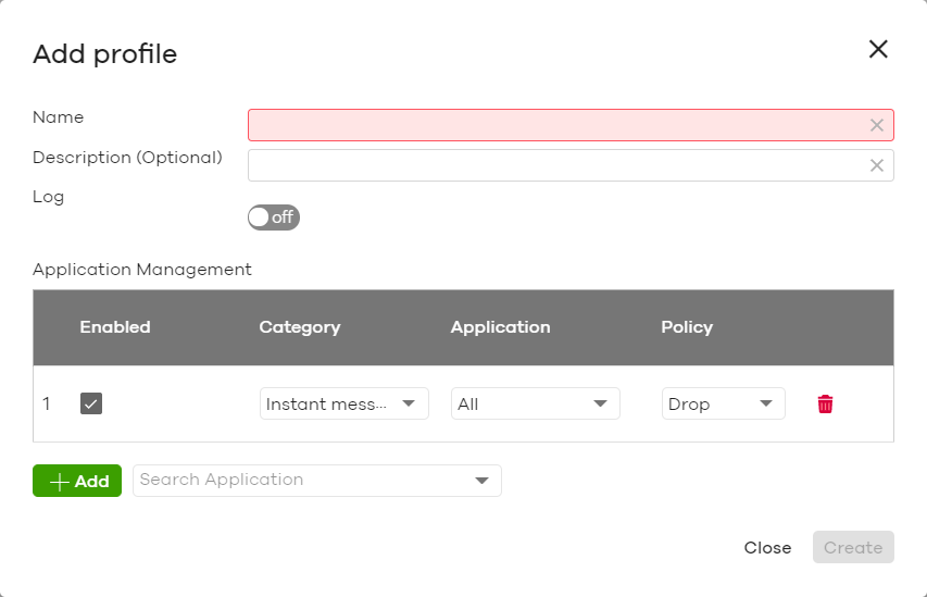
The following table describes the labels in this screen.
Label | Description |
|---|---|
Name | Enter a name for this profile for identification purposes. |
Description | Enter a description for this profile. |
Log | Select whether to have the Nebula Device generate a log (ON) or not (OFF) by default when traffic matches an application signature in this category. |
Application management | |
Enabled | Select the check box to turn on the rule. Otherwise, clear the check box to turn off the rule. |
Category | Select an application category. |
Application | Select All or select an application within the category to apply the policy. |
Policy | Select the default action for the applications selected in this category. Forward – the Nebula Device routes packets that matches these application signatures. Drop – the Nebula Device silently drops packets that matches these application signatures without notification. Reject – the Nebula Device drops packets that matches these application signatures and sends notification to clients. |
| Click this icon to remove the entry. |
Add | Click this button to create a new application category and set actions for specific applications within the category. |
Enter a name to search for relevant applications and click Add to create an entry. | |
Close | Click this button to exit this screen without saving. |
Create | Click this button to save your changes and close the screen. |
Create new schedule
Click the Add button in the Schedule Profiles section of the Security gateway > Configure > Firewall screen to access this screen.
Security gateway > Configure > Firewall: Add a schedule profile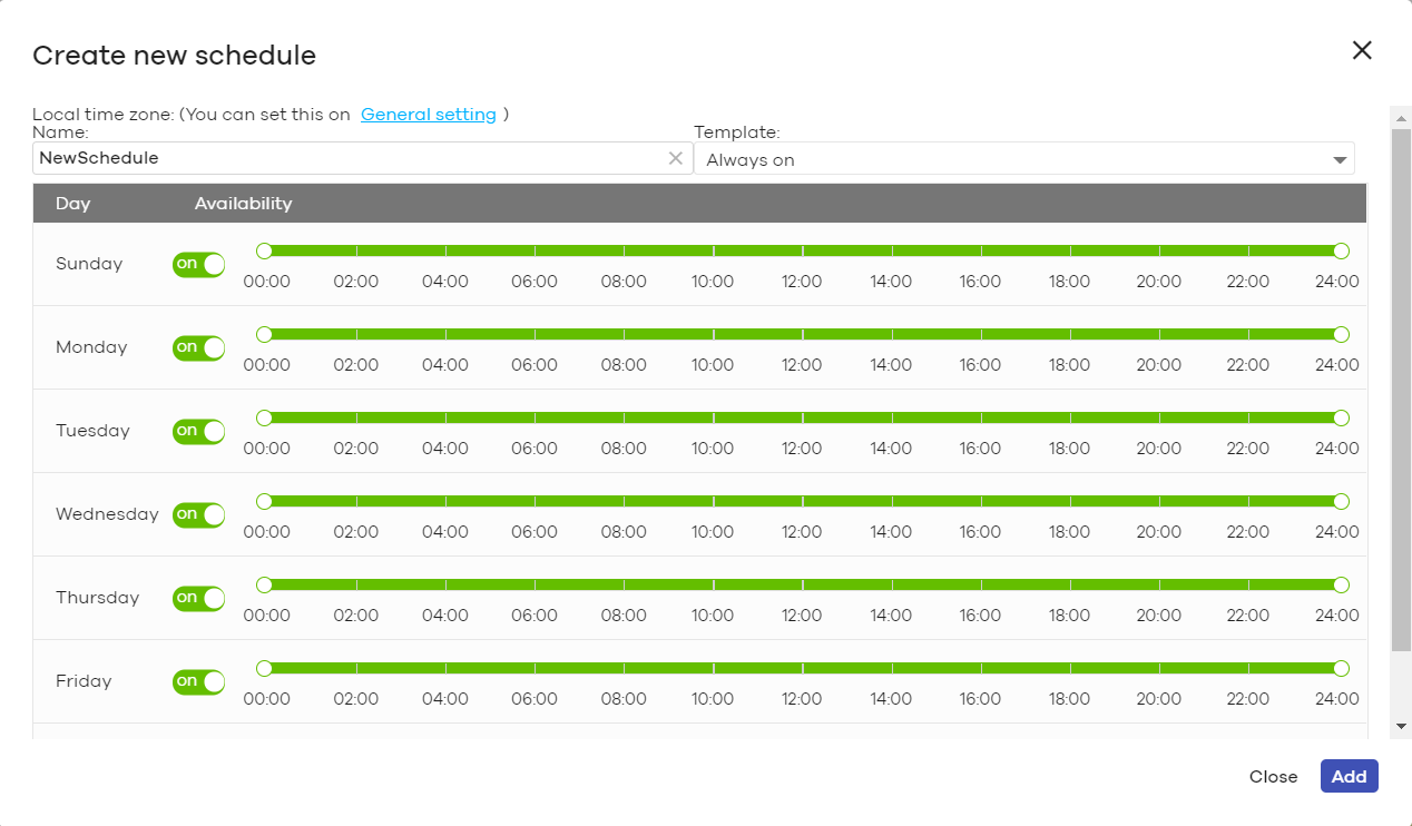
The following table describes the labels in this screen.
Label | Description |
|---|---|
Name | Enter a descriptive name for this schedule for identification purposes. |
Templates | Select a pre-defined schedule template or select Custom schedule and manually configure the day and time at which the associated firewall outbound rule is enabled. |
Day | This shows the day of the week. |
Availability | Click On to enable the associated rule at the specified time on this day. Otherwise, select Off to turn the associated rule off at the specified time on this day. Specify the hour and minute when the schedule begins and ends each day. |
Close | Click this button to exit this screen without saving. |
Add | Click this button to save your changes and close the screen. |
Security Service
Use this screen to enable or disable the features available in the security pack for your Nebula Device, such as content filtering, Intrusion Detection and Prevention (IDP) and/or anti-virus. As to application patrol, go to the Firewall screen to configure it since you need to have a firewall rule for outbound traffic.
Content filtering allows you to block access to specific web sites. It can also block access to specific categories of web site content. IDP can detect malicious or suspicious packets used in network-based intrusions and respond instantaneously. Anti-virus helps protect your connected network from virus/spy-ware infection.
Click Security gateway > Configure > Security service to access this screen.
Security gateway > Configure > Security service
The following table describes the labels in this screen.
Label | Description |
|---|---|
Content Filtering | |
Enabled | Click ON to enable the content filtering feature on the Nebula Device. Otherwise, click OFF to disable it. |
Interface | This shows the name of the interfaces created on the Nebula Device. Click ON to enable content filtering on the interfaces. |
Denied access message | Enter a message to be displayed when content filter blocks access to a web page. Use up to 127 characters (0–9a–zA–Z;/?:@&=+$\.-_!~*'()%,”). For example, “Access to this web page is not allowed. Please contact the network administrator”. It is also possible to leave this field blank if you have a URL specified in the Redirect URL field. In this case if the content filter blocks access to a web page, the Nebula Device just opens the web page you specified without showing a denied access message. |
Redirect URL | Enter the URL of the web page to which you want to send users when their web access is blocked by content filter. The web page you specify here opens in a new frame below the denied access message. Use “http://” or “https://” followed by up to 262 characters (0–9a–zA–Z;/?:@&=+$\.-_!~*'()%). For example, http://192.168.1.17/blocked access. |
Black list | Sites that you want to block access to, regardless of their content rating, can be blocked by adding them to this list. Enter host names such as www.bad-site.com into this text field. Do not enter the complete URL of the site – that is, do not include “http://”. All sub-domains are also blocked. For example, entering “bad-site.com” also blocks “www.badsite.com”, “partner.bad-site.com”, “press.bad-site.com”, and so on. You can also enter just a top level domain. For example, enter .com to block all .com domains. Use up to 127 characters (0–9a–z–). The casing does not matter. |
White list | Sites that you want to allow access to, regardless of their content rating, can be allowed by adding them to this list. Enter host names such as www.good-site.com into this text field. Do not enter the complete URL of the site – that is, do not include “http://”. All sub-domains are allowed. For example, entering “zyxel.com” also allows “www.zyxel.com”, “partner.zyxel.com”, “press.zyxel.com”, and so on. You can also enter just a top level domain. For example, enter .com to allow all .com domains. Use up to 127 characters (0–9a–z–). The casing does not matter. |
Block Category The Nebula Device prevents users from accessing web pages that match the categories that you select below. When external database content filtering blocks access to a web page, it displays the denied access message that you configured in the Denied access message field along with the category of the blocked web page. | |
Templates | Web pages are classified into a category based on their content. You can choose a pre-defined template that has already selected certain categories. Alternatively, choose Custom and manually select categories in this section to control access to specific types of Internet content. |
Test URL | You can check which category a web page belongs to. Enter a web site URL in the text box. When the content filter is active, you should see the web page’s category. The query fails if the content filter is not active. Content Filtering can query a category by full URL string (for example, http://www.google.com/picture/index.htm), but HTTPS Domain Filter can only query a category by domain name ('www.google.com'), so the category may be different in the query result. Test URL displays both results in the test. |
Search Category | Specify your desired filter criteria to filter the list of categories. |
Category List | Click to display or hide the category list. These are categories of web pages based on their content. Select categories in this section to control access to specific types of Internet content. |
Anti-Virus | |
Signature Information | This shows the Current Version of the anti-virus definition, its Signature Number and the Released Date. |
Enabled | Click On to enable anti-virus on the Nebula Device. Otherwise, select Off to disable it. |
Black/White List | Use this to set up anti-virus black (blocked) and white (allowed) lists of virus file patterns. |
File Pattern | For a black list entry, specify a pattern to identify the names of files that the Nebula Device should log and delete. For a white list entry, specify a pattern to identify the names of files that the Nebula Device should not scan for viruses. • Use up to 80 characters. Alphanumeric characters, underscores (_), dashes (-), question marks (?) and asterisks (*) are allowed. • A question mark (?) lets a single character in the file name vary. For example, use “a?.zip” (without the quotation marks) to specify aa.zip, ab.zip and so on. • Wildcards (*) let multiple files match the pattern. For example, use “*a.zip” (without the quotation marks) to specify any file that ends with “a.zip”. A file named “testa.zip would match. There could be any number (of any type) of characters in front of the “a.zip” at the end and the file name would still match. A file named “test.zipa” for example would not match. • An * in the middle of a pattern has the Nebula Device check the beginning and end of the file name and ignore the middle. For example, with “abc*.zip”, any file starting with “abc” and ending in “.zip” matches, no matter how many characters are in between. • The whole file name has to match if you do not use a question mark or asterisk. • If you do not use a wildcard, the Nebula Device checks up to the first 80 characters of a file name. |
Intrusion Detection / Prevention System | |
Signature Information | This shows the Current Version of the anti-intrusion definition, its Signature Number and the Released Date. |
Detection | Click On to detect malicious or suspicious packets. Otherwise, select Off to disable it. |
Prevention | Click On to identify and respond to intrusions. Otherwise, select Off to disable it. |
Site-to-Site VPN
A virtual private network (VPN) provides secure communications between sites without the expense of leased site-to-site lines. Use this screen to configure a VPN rule.
Click Security gateway > Configure > Site-to-Site VPN to access this screen.
Security gateway > Configure > Site-to-Site VPN
The following table describes the labels in this screen.
Label | Description |
|---|---|
Outgoing Interface | Select the WAN interface to which the VPN connection is going. Select AUTO to send VPN traffic through a different WAN interface when the primary WAN interface is down or disabled. |
Preferred uplink | Specify the primary WAN interface through which the Nebula Device forwards VPN traffic when you set Outgoing Interface to AUTO. |
Local networks | This shows the local networks behind the Nebula Device. |
Name | This shows the network name. |
Subnet | This shows the IP address and subnet mask of the computer on the network. |
Use VPN | Click this to allow or disallow the computer connected to the LAN port to use VPN. |
VPN Area | Select the VPN area of the site. For details, see VPN Areas. |
Nebula VPN enable | Click this to enable or disable site-to-site VPN on the site’s Nebula Device. If you disable this setting, the site will leave the VPN area. |
Nebula VPN Topology | This shows the VPN mode supported by the Nebula Device. Select a VPN topology. Select Disable to not set a VPN connection. In the Site-to-Site VPN topology, the remote IPSec device has a static IP address or a domain name. This Nebula Device can initiate the VPN tunnel. In the Hub-and-Spoke VPN topology, there is a VPN connection between each spoke router and the hub router, which uses the VPN concentrator. The VPN concentrator routes VPN traffic between the spoke routers and itself. In the Server-and-Client VPN topology, incoming connections from IPSec VPN clients are allowed. The clients have dynamic IP addresses and are also known as dial-in users. Only the clients can initiate the VPN tunnel. |
Branch to branch VPN | Enable this to allow spoke sites to communicate with each other in the VPN area. When disabled, spoke sites can only communicate with hub sites. |
Hubs (peers to connect to) | This field is available when you set Topology to Hub-and-Spoke. The field is configurable only when the Nebula Device of the selected site is the hub router. You can select another site’s name to have the Nebula Device of that site act as the hub router in the Hub-and-Spoke VPN topology. |
Area communication | Enable this to allow the site to communicate with sites in different VPN areas within the organization. |
NAT traversal | If the Nebula Device is behind a NAT router, enter the public IP address or the domain name that is configured and mapped to the Nebula Device on the NAT router. |
Server (client connect to) | This field is available when you set Topology to Server-and-Client. The field is configurable only when the Nebula Device of the selected site is the VPN server. You can select another site’s name to have the Nebula Device of that site act as the VPN server. |
Client-to-Client communication | Select On to allow VPN traffic to transmit between VPN clients by going through the server. The field is configurable only when the Nebula Device of the selected site is the VPN server. |
Remote VPN participants | This shows the remote (peer) Nebula Device’s network name and address. |
Non-Nebula VPN peers | If the remote VPN gateway is not a Nebula Device, use this section to set up a VPN connection between it and the Nebula Device. |
+ Add | Click this button to add a non-Nebula gateway to the VPN area. |
Enabled | Select the check box to turn on the rule. Otherwise, clear the check box to turn off the rule. |
Name | Enter the name of the peer gateway. |
Public IP | Enter the public IP address of the peer gateway. |
Private subnet | Enter the local network address or subnet behind the peer gateway. |
IPSec policy | Click to select a pre-defined policy or have a custom one. See Custom IPSec Policy for detailed information. |
Preshared secret | Enter a pre-shared key (password). The Nebula Device and peer gateway use the key to identify each other when they negotiate the IKE SA. |
Availability | Select All sites to allow the peer gateway to connect to any Nebula Device in the organization through a VPN tunnel. Select This site and the peer gateway can only connect to the Nebula Device in this site through a VPN tunnel. You can also configure any specific sites in the organization, |
Address | Enter the address (physical location) of the device. |
Remove | Click the remove icon to delete the entry. |
Add | Click this button to add a peer VPN gateway to the list. |
Custom IPSec Policy
Click an existing IPSec Policy button in the Non-Nebula VPN peers section of the Security gateway > Configure > Site-to-Site VPN screen to access this screen.
Security gateway > Configure > Site-to-Site VPN: Custom IPSec Policy
The following table describes the labels in this screen.
Label | Description |
|---|---|
Preset | Select a pre-defined IPSec policy, or select Custom to configure the policy settings yourself. |
Phase 1 | IPSec VPN consists of two phases: Phase 1 (Authentication) and Phase 2 (Key Exchange). A phase 1 exchange establishes an IKE SA (Security Association). |
IKE version | Select IKEv1 or IKEv2. IKEv1 applies to IPv4 traffic only. IKEv2 applies to both IPv4 and IPv6 traffic. IKE (Internet Key Exchange) is a protocol used in setting up security associations that allows two parties to send data securely. |
Encryption | Select which key size and encryption algorithm to use in the IKE SA. Choices are: DES – a 56-bit key with the DES encryption algorithm 3DES – a 168-bit key with the DES encryption algorithm AES128 – a 128-bit key with the AES encryption algorithm AES192 – a 192-bit key with the AES encryption algorithm AES256 – a 256-bit key with the AES encryption algorithm The Nebula Device and the remote IPSec router must use the same key size and encryption algorithm. Longer keys require more processing power, resulting in increased latency and decreased throughput. |
Authentication | Select which hash algorithm to use to authenticate packet data in the IKE SA. Choices are SHA128, SHA256, SHA512 and MD5. SHA is generally considered stronger than MD5, but it is also slower. The remote IPSec router must use the same authentication algorithm. |
Diffie-Hellman group | Select which Diffie-Hellman key group (DHx) you want to use for encryption keys. Choices are: DH1 – use a 768-bit random number DH2 – use a 1024-bit random number DH5 – use a 1536-bit random number DH14 – use a 2048-bit random number The longer the key, the more secure the encryption, but also the longer it takes to encrypt and decrypt information. Both routers must use the same DH key group. |
Lifetime (seconds) | Type the maximum number of seconds the IKE SA can last. When this time has passed, the Nebula Device and remote IPSec router have to update the encryption and authentication keys and re-negotiate the IKE SA. This does not affect any existing IPSec SAs, however. |
Advanced | Click this to display a greater or lesser number of configuration fields. |
Mode | Select the negotiation mode to use to negotiate the IKE SA. Choices are: Main – this encrypts the Nebula Device’s and remote IPSec router’s identities but takes more time to establish the IKE SA Aggressive – this is faster but does not encrypt the identities The Nebula Device and the remote IPSec router must use the same negotiation mode. |
Local ID | Enter the identity of the Nebula Device during authentication. Any indicates that the remote IPSec router does not check the identity of the Nebula Device. |
Peer ID | Enter the identity of the remote IPSec router during authentication. Any indicates that the Nebula Device does not check the identity of the remote IPSec router. |
Phase 2 | Phase 2 uses the SA that was established in phase 1 to negotiate SAs for IPSec. |
Encryption | Select which key size and encryption algorithm to use in the IPSec SA. Choices are: (none) – no encryption key or algorithm DES – a 56-bit key with the DES encryption algorithm 3DES – a 168-bit key with the DES encryption algorithm AES128 – a 128-bit key with the AES encryption algorithm AES192 – a 192-bit key with the AES encryption algorithm AES256 – a 256-bit key with the AES encryption algorithm The Nebula Device and the remote IPSec router must both have at least one proposal that uses use the same encryption and the same key. Longer keys are more secure, but require more processing power, resulting in increased latency and decreased throughput. |
Authentication | Select which hash algorithm to use to authenticate packet data in the IPSec SA. Choices are None, MD5, SHA128, SHA256, and SHA512. SHA is generally considered stronger than MD5, but it is also slower. The Nebula Device and the remote IPSec router must both have a proposal that uses the same authentication algorithm. |
PFS group | Select whether or not you want to enable Perfect Forward Secrecy (PFS) and, if you do, which Diffie-Hellman key group to use for encryption. Choices are: None – disable PFS DH1 – enable PFS and use a 768-bit random number DH2 – enable PFS and use a 1024-bit random number DH5 – enable PFS and use a 1536-bit random number DH14 – enable PFS and use a 2048-bit random number PFS changes the root key that is used to generate encryption keys for each IPSec SA. The longer the key, the more secure the encryption, but also the longer it takes to encrypt and decrypt information. Both routers must use the same DH key group. PFS is ignored in initial IKEv2 authentication but is used when re-authenticating. |
Lifetime (seconds) | Enter the maximum number of seconds the IPSec SA can last. Shorter life times provide better security. The Nebula Device automatically negotiates a new IPSec SA before the current one expires, if there are users who are accessing remote resources. |
VPN tunnel interface (optional) IPSec VPN Tunnel Interface (VTI) encrypts or decrypts IPv4 traffic from or to the interface according to the IP routing table. VTI allows static routes to send traffic over the VPN. The IPSec tunnel endpoint is associated with an actual (virtual) interface. Therefore many interface capabilities such as Policy Route, Static Route, Trunk, and BWM can be applied to the IPSec tunnel as soon as the tunnel is active. IPSec VTI simplifies network management and load balancing. Create a trunk using VPN tunnel interfaces for load balancing. This section is available when you select IKEv2 in the IKE Version field. | |
IP address | Enter the IP address of the VPN tunnel interface. |
Subnet mask | Enter the subnet mask of this interface in dot decimal notation. The subnet mask indicates what part of the IP address is the same for all computers in the network |
Close | Click this button to exit this screen without saving. |
OK | Click this button to save your changes and close the screen. |
Remote Access VPN
Use this screen to configure the VPN client settings.
Internet Protocol Security (IPSec) VPN connects IPSec routers or remote users using IPSec client software. This standards-based VPN offers flexible solutions for secure data communications across a public network. IPSec is built around a number of standardized cryptographic techniques to provide confidentiality, data integrity and authentication at the IP layer.
The Layer 2 Tunneling Protocol (L2TP) works at layer 2 (the data link layer) to tunnel network traffic between two peers over another network (like the Internet). In L2TP VPN, an IPSec VPN tunnel is established first and then an L2TP tunnel is built inside it.
Click Security gateway > Configure > Remote access VPN to access this screen.
Security gateway > Configure > Remote access VPN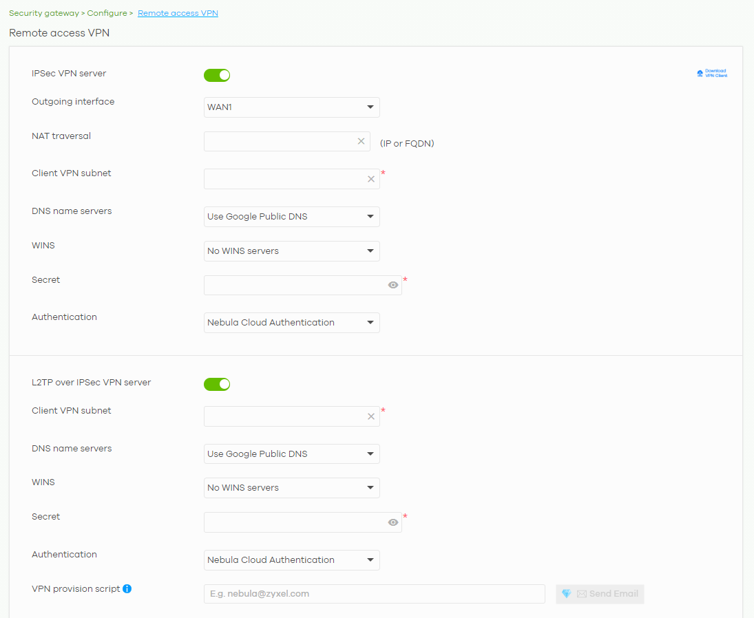
The following table describes the labels in this screen.
Label | Description |
|---|---|
Click this icon to download VPN client software. | |
IPSec VPN server | Select to enable the IPSec client feature on the Nebula Device. Otherwise, select Disable to turn it off. |
Outgoing interface | Select the WAN interface to which the IPSec VPN connection is going. |
NAT traversal | Enter the IP address or domain name of the NAT router if the IPSec VPN tunnel must pass through NAT (there is a NAT router between the IPSec devices). |
Client VPN subnet | Specify the IP addresses that the Nebula Device uses to assign to the IPSec VPN clients. |
DNS name servers | Specify the IP addresses of DNS servers to assign to the remote users. Select Use Google Public DNS to use the DNS service offered by Google. Otherwise, select Specify nameserver to enter a static IP address. |
Custom nameservers | If you select Specify nameserver in the DNS name servers field, manually enter the DNS server IP addresses. |
WINS | The WINS (Windows Internet Naming Service) server keeps a mapping table of the computer names on your network and the IP addresses that they are currently using. Select No WINS Servers to not send WINS server addresses to the users. Otherwise, select Specify nameserver to enter the IP addresses of WINS servers to assign to the remote users. |
Custom nameservers | If you select Specify nameserver in the WINS field, manually enter the WINS server IP addresses. |
Secret | Enter the pre-shared key (password) which is used to set up the IPSec VPN tunnel. |
Authentication | Select how the Nebula Device authenticates a remote user before allowing access to the IPSec VPN tunnel. |
L2TP over IPSec VPN server | Select to enable the L2TP over IPSec VPN feature on the Nebula Device. Otherwise, select Disable to turn it off. |
Client VPN subnet | Specify the IP addresses that the Nebula Device uses to assign to the L2TP over IPSec VPN clients. |
DNS name servers | Specify the IP addresses of DNS servers to assign to the remote users. Select Use Google Public DNS to use the DNS service offered by Google. Otherwise, select Specify nameserver to enter a static IP address. |
Custom nameservers | If you select Specify nameserver in the DNS name servers field, manually enter the DNS server IP addresses. |
WINS | The WINS (Windows Internet Naming Service) server keeps a mapping table of the computer names on your network and the IP addresses that they are currently using. Select No WINS Servers to not send WINS server addresses to the users. Otherwise, select Specify nameserver to enter the IP addresses of WINS servers to assign to the remote users. |
Custom nameservers | If you select Specify nameserver in the WINS field, manually enter the WINS server IP addresses. |
Secret | Enter the pre-shared key (password) which is used to set up the L2TP over IPSec VPN tunnel. |
Authentication | Select how the Nebula Device authenticates a remote user before allowing access to the L2TP over IPSec VPN tunnel. |
VPN provision script | Send an email to help automatically configure VPN settings on client devices so that the devices can remotely access this Nebula Device. The email contains two scripts; one for mac OS and iOS devices, and one for Windows 8 and Windows 10 devices. You can send the email to one or more email addresses. • If Authentication is set to Nebula Cloud Authentication, the default email address list contains all authorized VPN user email addresses and your email address. • If Authentication is set to AD and RADIUS Authentication, the default email address list contains your user email address. |
Captive Portal
Use this screen to configure captive portal settings for each interface. A captive portal can intercept network traffic until the user authenticates his or her connection, usually through a specifically designated login web page.
Click Security gateway > Configure > Captive portal to access this screen.
Security gateway > Configure > Captive portal
The following table describes the labels in this screen.
Label | Description |
|---|---|
Interface | Select the Nebula Device’s interface (network) to which the settings you configure here is applied. |
Themes | This section is not configurable when External captive portal URL is set to ON. • Click the Preview icon at the upper right of a theme image to display the portal page in a new frame. • Click the Copy icon to create a new custom theme (portal page). • Click the Edit icon of a custom theme to go to a screen, where you can view and configure the details of the custom portal pages. See Custom Theme Edit. • Click the Remove icon to delete a custom theme. Select the theme you want to use on the specified interface. |
Click-to-continue/Sign-on page This section is not configurable when External captive portal URL is set to ON. | |
Logo | This shows the logo image that you uploaded for the customized login page. Click Upload a logo and specify the location and file name of the logo graphic or click Browse to locate it. You can use the following image file formats: GIF, PNG, or JPG. |
Message | Enter a note to display below the title. Use up to 1024 printable ASCII characters. Spaces are allowed. |
Success page | |
Message | Enter a note to display on the page that displays when a user logs in successfully. Use up to 1024 printable ASCII characters. Spaces are allowed. |
External captive portal URL | |
Use URL | Select On to use a custom login page from an external web portal instead of the one built into the NCC. You can configure the look and feel of the web portal page. Specify the login page’s URL; for example, http://IIS server IP Address/login.asp. The Internet Information Server (IIS) is the web server on which the web portal files are installed. |
Captive portal behavior | |
After the captive portal page where the user should go? | Select To promotion URL and specify the URL of the web site/page to which the user is redirected after a successful login. Otherwise, select Stay on Captive portal authenticated successfully page. |
Custom Theme Edit
Use this screen to check what the custom portal pages look like. You can also view and modify the CSS values of the selected HTML file. Click a custom login page’s Edit button in the Security gateway > Configure > Captive portal screen to access this screen.
Security gateway > Configure > Captive portal: Edit
The following table describes the labels in this screen.
Label | Description |
|---|---|
Back to config | Click this button to return to the Captive portal screen. |
Theme name | This shows the name of the theme. Click the edit icon to change it. |
Font | Click the arrow to hide or display the configuration fields. To display this section and customize the font type and/or size, click an item with text in the preview of the selected custom portal page (HTML file). |
Color | Click the arrow to hide or display the configuration fields. Click an item in the preview of the selected custom portal page (HTML file) to display this section and customize its color, such as the color of the button, text, window’s background, links, borders, and so on. Select a color that you want to use and click the Select button. |
HTML/CSS | This shows the HTML file name of the portal page created for the selected custom theme. This also shows the name of the CSS files created for the selected custom theme. Click an HTML file to display the portal page. You can also change colors and modify the CSS values of the selected HTML file. |
Click this button to view and modify the CSS values of the selected HTML file. It is recommended that you do NOT change the script code to ensure proper operation of the portal page. | |
Click this button to preview the portal page (the selected HTML file). | |
Save | Click this button to save your settings for the selected HTML file to the NCC. |
Apply | Click this button to save your settings for the selected HTML file to the NCC and apply them to the Nebula Device in the site. |
Network Access Method
Use this screen to enable or disable web authentication on an interface.
Click Security gateway > Configure > Network access method to access this screen.
Security gateway > Configure > Network access method
The following table describes the labels in this screen.
Label | Description |
|---|---|
Interfaces | Select the Nebula Device’s interface (network) to which the settings you configure here is applied. |
Network Access | Select Disable to turn off web authentication. Select Click-to-continue to block network traffic until a client agrees to the policy of user agreement. Select Sign-on with to block network traffic until a client authenticates with an external RADIUS or AD server through the specifically designated web portal page. Select Nebula Cloud Authentication or an authentication server that you have configured in the Security gateway > Configure > Gateway settings screen (see Gateway Settings). Select Two-Factor Authentication to require that the user log in using both their password and a Google Authenticator code. To log in, users must have Two-Factor Authentication enabled on their account and have setup Google Authenticator on their mobile device. |
Walled garden | This field is not configurable if you set Network Access to Disable. Select to turn on or off the walled garden feature. With a walled garden, you can define one or more web site addresses that all users can access without logging in. These can be used for advertisements for example. |
Walled garden ranges | Specify walled garden web site links, which use a domain name or an IP address for web sites that all users are allowed to access without logging in. |
Captive portal access attribute | |
Self-registration | This field is available only when you select Sign-on with Nebula Cloud authentication in the Network Access field. Select Allow users to create accounts with auto authorized or Allow users to create accounts with manual authorized to display a link in the captive portal login page. The link directs users to a page where they can create an account before they authenticate with the NCC. For Allow users to create accounts with manual authorized, users cannot log in with the account until the account is authorized and granted access. For Allow users to create accounts with auto authorized, users can just use the registered account to log in without administrator approval. Select Don’t allow users to create accounts to not display a link for account creation in the captive portal login page. |
Login on multiple client devices | This field is available only when you select Sign-on with in the Network Access field. Select Multiple devices access simultaneously if you allow users to log in as many times as they want as long as they use different IP addresses. Select One device at a time if you do NOT allow users to have simultaneous logins. |
NCAS disconnection behavior | This field is available only when you select Sign-on with Nebula Cloud Authentication in the Network Access field. Select Allowed to allow any users to access the network without authentication when the NCAS (Nebula Cloud Authentication Server) is not reachable. Select Limited to allow only the currently connected users or the users in the white list to access the network. |
Traffic Shaping
Use this screen to configure maximum bandwidth and load balancing on the Nebula Device.
Click Security gateway > Configure > Traffic shaping to access this screen.
Security gateway > Configure > Traffic shaping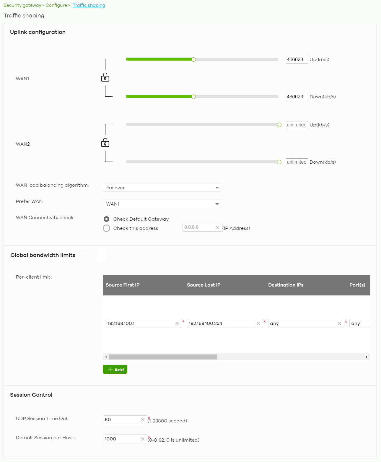
The following table describes the labels in this screen.
Label | Description |
|---|---|
Uplink configuration | |
WAN 1 WAN 2 | Set the amount of upstream/downstream bandwidth for the WAN interface. Click a lock icon to change the lock state. If the lock icon for a WAN interface is locked, the bandwidth limit you set applies to both inbound and outbound traffic. If the lock is unlocked, you can set inbound and outbound traffic to have different transmission speeds. |
WAN load balancing algorithm | Select a load balancing method to use from the drop-down list box. • Select Least Load First to send new session traffic through the least utilized WAN interface. • Select Round Robin to balance the traffic load between interfaces based on their respective weights (bandwidth). An interface with a larger weight gets more chances to transmit traffic than an interface with a smaller weight. For example, if the weight ratio of WAN 1 and WAN 2 interfaces is 2:1, the Nebula Device chooses WAN 1 for two sessions’ traffic and WAN 2 for one session’s traffic in each round of three new sessions. • Select Failover to send traffic through a second WAN interface when the primary WAN interface is down or disabled. |
Prefer WAN | Specify the primary WAN interface through which the Nebula Device forwards traffic. This field is available when you set WAN load balancing algorithm to Failover. |
WAN Connectivity check | The interface can regularly check the connection to the gateway you specified to make sure it is still available. The Nebula Device resumes routing to the gateway the first time the gateway passes the connectivity check. If the WAN connection is down (the check fails), the Nebula Device will switch (failover) to use a redundant WAN connection. • Select Check Default Gateway to use the default gateway for the connectivity check. • Select Check this address to specify a domain name or IP address for the connectivity check. This field is available when you set WAN load balancing algorithm to Failover. |
Global bandwidth limits | |
Per-client limit | You can limit a client’s outbound or inbound bandwidth. |
Source First IP | Enter the first IP address in a range of source IP addresses for which the Nebula Device applies the rule. |
Source Last IP | Enter the last IP address in a range of source IP addresses for which the Nebula Device applies the rule. |
Destination IPs | Enter the destination IP addresses for which the Nebula Device applies the rule. Enter any if the rule is effective for every destination. |
Port(s) | Enter the port numbers (1 – 65535) to which the packets go. The Nebula Device applies the rule to the packets that go to the corresponding service port. any means all service ports. |
Protocol | Select TCP or UDP if you want to specify a protocol for the rule. Otherwise select Any. Any means the rule is applicable to all services. |
Down/Up | Set the maximum upstream/downstream bandwidth for traffic from an individual source IP address. Click a lock icon to change the lock state. If the lock icon is locked, the bandwidth limit you set applies to both inbound and outbound traffic. If the lock is unlocked, you can set inbound and outbound traffic to have different transmission speeds. |
Priority | Enter a number between 1 and 7 to set the priority for traffic that matches this policy. The smaller the number, the higher the priority. Traffic with a higher priority is given bandwidth before traffic with a lower priority. |
| Click this icon to remove the rule. |
Add | Click this button to create a new rule. |
Session Control | |
UDP Session Time Out | Set how many seconds the Nebula Device will allow a UDP session to remain idle (without UDP traffic) before closing it. |
Default Session per Host | Set a common limit to the number of concurrent NAT/Security Policy sessions each client computer can have. If only a few clients use peer to peer applications, you can raise this number to improve their performance. With heavy peer to peer application use, lower this number to ensure no single client uses too many of the available NAT sessions. |
Gateway Settings
Use this screen to configure DNS settings and external AD (Active Directory) server or RADIUS server that the Nebula Device can use in authenticating users.
AD (Active Directory) is a directory service that is both a directory and a protocol for controlling access to a network. The directory consists of a database specialized for fast information retrieval and filtering activities. You create and store user profile and login information on the external server.
This screen also lets you configure the addresses of walled garden web sites that users can access without logging into the Nebula Device. The settings in this screen apply to all networks (interfaces) on the Nebula Device. If you want to configure walled garden web site links for a specific interface, use the Network access method screen.
Click Security gateway > Configure > Gateway settings to access this screen.
Security gateway > Configure > Gateway settings
The following table describes the labels in this screen.
Label | Description |
|---|---|
DNS | |
Address Record | This record specifies the mapping of a Fully-Qualified Domain Name (FQDN) to an IP address. An FQDN consists of a host and domain name. For example, www.zyxel.com.tw is a fully qualified domain name, where “www” is the host, “zyxel” is the third-level domain, “com” is the second-level domain, and “tw” is the top level domain. |
FQDN | Enter a host’s fully qualified domain name. Use "*." as a prefix in the FQDN for a wildcard domain name (for example, *.example.com). |
IP Address | Enter the host’s IP address. |
| Click this icon to remove the entry. |
Add | Click this button to create a new entry. |
Domain Zone Forwarder | This specifies a DNS server’s IP address. The Nebula Device can query the DNS server to resolve domain zones for features like VPN, DDNS and the time server. When the Nebula Device needs to resolve a domain zone, it checks it against the domain zone forwarder entries in the order that they appear in this list. |
Domain Zone | A domain zone is a fully qualified domain name without the host. For example, zyxel.com.tw is the domain zone for the www.zyxel.com.tw fully qualified domain name. Whenever the Nebula Device needs to resolve a zyxel.com.tw domain name, it can send a query to the recorded name server IP address. |
IP Address | Enter the DNS server's IP address. |
Interface | Select the interface through which the Nebula Device sends DNS queries to the specified DNS server. |
| Click this icon to remove the entry. |
Add | Click this button to create a new entry. |
Authentication Server My AD Server | |
Name | Enter a descriptive name for the server. |
Server address | Enter the address of the AD server. |
Backup server address | If the AD server has a backup server, enter its address here. |
Port | Specify the port number on the AD server to which the Nebula Device sends authentication requests. Enter a number between 1 and 65535. |
AD domain | Specify the Active Directory forest root domain name. |
Domain admin | Enter the name of the user that is located in the container for Active Directory Users, who is a member of the Domain Admin group. |
Password | Enter the password of the Domain Admin user account. |
Advanced | Click to open a screen where you can select to use Default or Custom advanced settings. See Advanced Settings. |
| Click this icon to remove the server. |
Add | Click this button to create a new server. |
My RADIUS server | |
Name | Enter a descriptive name for the server. |
Server address | Enter the address of the RADIUS server. |
Backup server address | If the RADIUS server has a backup server, enter its address here. |
Port | Specify the port number on the RADIUS server to which the Nebula Device sends authentication requests. Enter a number between 1 and 65535. |
Secret | Enter a password (up to 15 alphanumeric characters) as the key to be shared between the external authentication server and the Nebula Device. The key is not sent over the network. This key must be the same on the external authentication server and the Nebula Device. |
Advanced | Click to open a screen where you can select to use Default or Custom advanced settings. See Advanced Settings. |
| Click this icon to remove the server. |
Add | Click this button to create a new server. |
Walled garden | |
Global Walled garden | With a walled garden, you can define one or more web site addresses that all users can access without logging in. These can be used for advertisements for example. Specify walled garden web site links, which use a domain name or an IP address for web sites that all users are allowed to access without logging in. |
Advanced Settings
Click the Advanced column in the Security gateway > Configure > Gateway settings screen to access this screen.
Security gateway > Configure > Gateway settings: Advanced
The following table describes the labels in this screen.
Label | Description |
|---|---|
Preset | Select Default to use the pre-defined settings, or select Custom to configure your own settings. |
Timeout | Specify the timeout period (between 1 and 300 seconds) before the Nebula Device disconnects from the server. In this case, user authentication fails. Search timeout occurs when either the user information is not in the servers or the AD or server is down. |
Case-Sensitive User Name | Click ON if the server checks the case of the user name. Otherwise, click OFF to not configure your user name as case-sensitive. |
NAS IP Address | This field is only for RADIUS. Enter the IP address of the NAS (Network Access Server). |
Close | Click this button to exit this screen without saving. |
OK | Click this button to save your changes and close the screen. |