MAINTENANCE
Overview
This chapter explains how to configure the screens that let you maintain the firmware and configuration files.
What You Can Do
• Use the Certificates screen (Certificates) to see the Certificates screen and import the Switch's CA-signed certificates.
• Use the Cluster Management screens (Cluster Management Status) to manage the switches within a cluster and view cluster status.
• Use the Restore Configuration screen (Restore Configuration) to upload a stored device configuration file.
• Use the Backup Configuration screen (Backup Configuration) to save your configurations for later use.
• Use the Erase Running-Configuration screen (Erase Running-Configuration) to reset the configuration to the Zyxel default configuration settings.
• Use the Save Configuration screen (Save Configuration) to save the current configuration settings to a specific configuration file on the Switch.
• Use the Configure Clone screen (Configure Clone) to copy the basic and advanced settings from a source port to a destination port or ports.
• Use the Diagnostic screen (Diagnostic) to ping IP addresses, run a traceroute, perform port tests or show the Switch’s location between devices.
• Use the Reboot System screen (Reboot System) to restart the Switch without physically turning the power off and load a specific configuration file.
• Use the SSH Authorized Keys screen (SSH Authorized Keys) to authenticate secure SSH connections between a client computer and the Switch (also called the server) without needing a password to connect to the Switch.
• Use the SSH Host Keys screen (SSH Host Keys) to regenerate the Switch's SSH host key. You may want to do this to change the factory default SSH host key.
• Use the Tech-Support screen (Tech-Support) to create reports for customer support if there are problems with the Switch.
Certificates
The Switch can use HTTPS certificates that are verified by a third party to create secure HTTPS connections between your computer and the Switch. This way, you may securely access the Switch using the Web Configurator. See Introduction to HTTPS for more information about HTTPS.
Certificates are based on public-private key pairs. A certificate contains the certificate owner’s identity and public key. Certificates provide a way to exchange public keys for use in authentication.
Click MAINTENANCE > Certificates to open the following screen. Use this screen to import the Switch's CA-signed certificates.
MAINTENANCE > Certificates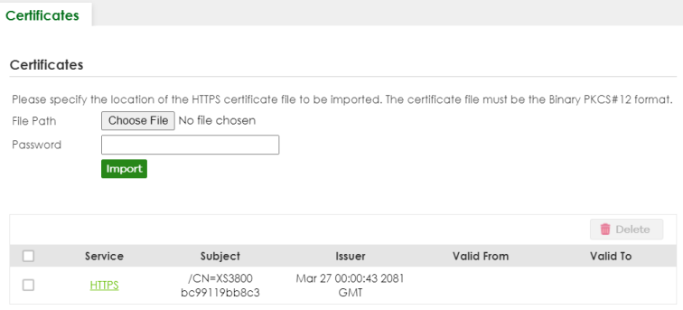
The following table describes the labels in this screen.
label | description |
|---|---|
File Path | Click Choose File or Browse to find the certificate file you want to upload. |
Password | Enter the certificate file’s password that was created when the PKCS #12 file was exported. The password consists of up to 32 printable ASCII characters except [ ? ], [ | ], [ ' ], [ " ] or [ , ]. |
Import | Click this button to save the certificate that you have enrolled from a certification authority from your computer to the Switch. |
Service | This field displays the service type that this certificate is for. |
Subject | This field displays identifying information about the certificate’s owner, such as CN (Common Name), OU (Organizational Unit or department), O (Organization or company) and C (Country). It is recommended that each certificate have unique subject information. |
Issuer | This field displays identifying information about the certificate’s issuing certification authority, such as a common name, organizational unit or department, organization or company and country. |
Valid From | This field displays the date that the certificate becomes applicable. |
Valid To | This field displays the date that the certificate expires. |
Select an entry’s checkbox to select a specific entry. | |
Delete | Click this button to delete the certificate (or certification request). You cannot delete a certificate that one or more features is configured to use. |
Install Certificates
After buying the certificates from a trusted third-party Certificate Authorities (CA), (for example, DigiCert), install the certificates. See Importing a Certificate for more information.
HTTPS Certificates
Use this screen to view the HTTPS certificate details. Click a hyperlink in the Service column in the MAINTENANCE > Certificates screen to open the following screen.
MAINTENANCE > Certificates > HTTPS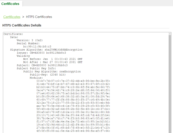
Technical Reference
This section provides technical background information on the topics discussed in this chapter.
FTP Command Line
This section shows some examples of uploading to or downloading files from the Switch using FTP commands. First, understand the filename conventions.
Filename Conventions
The configuration file (also known as the romfile or ROM) contains the Zyxel factory default configuration settings in the screens such as password, Switch setup, IP Setup, and so on. Once you have customized the Switch’s settings, they can be saved back to your computer under a filename of your choosing.
ZyNOS (Zyxel Network Operating System sometimes referred to as the “ras” file) is the system firmware and has a “bin” filename extension.
File Type | Internal Name | External Name | Description |
|---|---|---|---|
Configuration File | config1 config2 | *.cfg | This is the configuration filename on the Switch. Uploading the config file replaces the specified configuration file system, including your Switch configurations, system-related data (including the default password), the error log and the trace log. |
Firmware | ras | *.bin | This is the generic name for the ZyNOS firmware on the Switch. |
Example FTP Commands
ftp> put firmware.bin ras-0
This is a sample FTP session showing the transfer of the computer file "firmware.bin" to the Switch’s Firmware 1.
ftp> get config1 config1.cfg
This is a sample FTP session saving the Switch’s configuration file 1 (Config1) to a file called “config1.cfg” on your computer.
If your (T)FTP client does not allow you to have a destination filename different than the source, you will need to rename them as the Switch only recognizes “config” and “ras”. Be sure you keep unaltered copies of both files for later use.
Be sure to upload the correct model firmware as uploading the wrong model firmware may damage your device.
FTP Command Line Procedure
1 Launch the FTP client on your computer.
2 Enter open, followed by a space and the IP address of your Switch.
3 Press [ENTER] when prompted for a user name.
4 Enter your password as requested (the default is “1234”).
5 Enter bin to set transfer mode to binary.
6 Use put to transfer files from the computer to the Switch, for example, put firmware.bin ras transfers the firmware on your computer (firmware.bin) to the Switch and renames it to “ras”. Similarly, put config.cfg config1 transfers the configuration file on your computer (config.cfg) to the Switch and renames it to “config1”. Likewise get config1 config.cfg transfers the configuration file on the Switch to your computer and renames it to “config.cfg”. See Filename Conventions for more information on filename conventions.
7 Enter quit to exit the ftp prompt.
GUI-based FTP Clients
The following table describes some of the commands that you may see in GUI-based FTP clients.
command | Description |
|---|---|
Host Address | Enter the address of the host server. |
Login Type | Anonymous. This is when a user I.D. and password is automatically supplied to the server for anonymous access. Anonymous logins will work only if your ISP or service administrator has enabled this option. Normal. The server requires a unique User ID and Password to login. |
Transfer Type | Transfer files in either single-byte printable characters (plain text format) or in binary mode. Configuration and firmware files should be transferred in binary mode. |
Initial Remote Directory | Specify the default remote directory (path). |
Initial Local Directory | Specify the default local directory (path). |
FTP Restrictions
FTP will not work when:
• FTP service is disabled in the SECURITY > Access Control > Service Access Control screen.
• The IP addresses in the SECURITY > Access Control > Remote Management screen does not match the client IP address. If it does not match, the Switch will disconnect the FTP session immediately.
Cluster Management Overview
Cluster Management allows you to manage switches through one Switch, called the cluster manager. The switches must be directly connected and be in the same VLAN group so as to be able to communicate with one another.
Maximum number of cluster members | 24 |
Cluster Member Models | Must be compatible with Zyxel cluster management implementation. |
Cluster Manager | The Switch through which you manage the cluster member switches. |
Cluster Members | The switches being managed by the cluster manager Switch. |
In the following example, switch A in the basement is the cluster manager and the other switches on the upper floors of the building are cluster members.
Clustering Application Example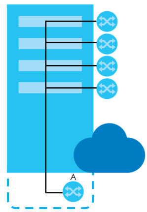
What You Can Do
• Use the Cluster Management Status screen (Cluster Management Status) to view the role of the Switch within the cluster and to access a cluster member Switch’s Web Configurator.
• Use the Cluster Management Setup screen (Clustering Management Setup) to configure clustering management.
Cluster Management Status
Use this screen to view the role of the Switch within the cluster and to access a cluster member Switch’s Web Configurator.
Click MAINTENANCE > Cluster Management in the navigation panel to display the following screen.
MAINTENANCE > Cluster Management > Cluster Management Status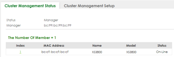
The following table describes the labels in this screen.
label | Description |
|---|---|
Status | This field displays the role of this Switch within the cluster. Manager Member (you see this if you access this screen in the cluster member Switch directly and not through the cluster manager) None (neither a manager nor a member of a cluster) |
Manager | This field displays the cluster manager Switch’s hardware MAC address. |
The Number Of Member | This field displays the number of switches that make up this cluster. The following fields describe the cluster member switches. |
Index | You can manage cluster member switches through the cluster manager Switch. Each number in the Index column is a hyperlink leading to the cluster member Switch’s Web Configurator. |
MAC Address | This is the cluster member Switch’s hardware MAC address. |
Name | This is the cluster member Switch’s System Name. |
Model | This field displays the model name. |
Status | This field displays: Online (the cluster member Switch is accessible) Error (for example the cluster member Switch password was changed or the Switch was set as the manager and so left the member list, and so on) Offline (the Switch is disconnected – Offline shows approximately 1.5 minutes after the link between cluster member and manager goes down) |
Clustering Management Setup
Use this screen to configure clustering management. Click MAINTENANCE > Cluster Management > Cluster Management Setup to display the next screen.
MAINTENANCE > Cluster Management > Cluster Management Setup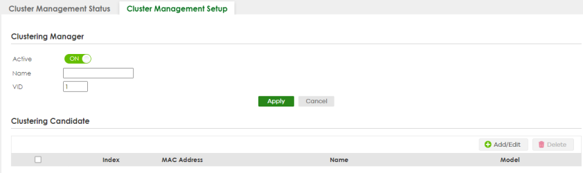
The following table describes the labels in this screen.
label | Description |
|---|---|
Clustering Manager | The following fields relate to configuring the cluster manager. |
Active | Enable the switch button to have this Switch become the cluster manager switch. A cluster can only have one manager. Other (directly connected) switches that are set to be cluster managers will not be visible in the Clustering Candidates list. If a Switch that was previously a cluster member is later set to become a cluster manager, then its Status is displayed as Error in the Cluster Management Status screen and a warning icon (  ) appears in the member summary list below. ) appears in the member summary list below. |
Name | Type a name to identify the Clustering Manager. You may use up to 32 printable ASCII characters except [ ? ], [ | ], [ ' ], [ " ] or [ , ]. (spaces are allowed). |
VID | This is the VLAN ID and is only applicable if the Switch is set to 802.1Q VLAN. All switches must be directly connected and in the same VLAN group to belong to the same cluster. Switches that are not in the same VLAN group are not visible in the Clustering Candidates list. This field is ignored if the Clustering Manager is using Port-based VLAN. |
Apply | Click Apply to save your changes to the Switch’s run-time memory. The Switch loses these changes if it is turned off or loses power, so use the Save link on the top navigation panel to save your changes to the non-volatile memory when you are done configuring. |
Cancel | Click Cancel to begin configuring this screen afresh. |
Clustering Candidate | The next summary table shows the information for the clustering members configured. |
Add/Edit | Click this button to create or configure a clustering candidate. |
Delete | Click this button to remove the clustering candidate. |
Select an entry’s checkbox to select a specific entry. Otherwise, select the checkbox in the table heading row to select all entries. | |
Index | This is the index number of a cluster member switch. |
MAC Address | This is the cluster member switch’s hardware MAC address. |
Name | This is the cluster member switch’s System Name. |
Model | This is the cluster member switch’s model name. |
Click the Add/Edit button to open the Add/Edit screen. Use this screen to configure a clustering candidate for the Switch.
MAINTENANCE > Cluster Management > Cluster Management Setup > Add/Edit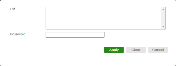
The following table describes the labels in this screen.
label | Description |
|---|---|
List | A list of suitable candidates found by auto-discovery is shown here. The switches must be directly connected. Directly connected switches that are set to be cluster managers will not be visible in the Clustering Candidate list. Switches that are not in the same management VLAN group will not be visible in the Clustering Candidate list. |
Password | Each cluster member’s password is its Web Configurator password. Select a member in the Clustering Candidate list and then enter its Web Configurator password. If that switch administrator changes the Web Configurator password afterwards, then it cannot be managed from the Cluster Manager. Its Status is displayed as Error in the Cluster Management Status screen. If multiple devices have the same password then hold [SHIFT] and click those switches to select them. Then enter their common Web Configurator password. You can enter up to 32 printable ASCII characters except [ ? ], [ | ], [ ' ], [ " ] or [ , ]. |
Apply | Click Apply to save your changes to the Switch’s run-time memory. The Switch loses these changes if it is turned off or loses power, so use the Save link on the top navigation panel to save your changes to the non-volatile memory when you are done configuring. |
Clear | Click Clear to reset the fields to the factory defaults. |
Cancel | Click Cancel to begin configuring this screen afresh. |
Technical Reference
This section provides technical background information on the topics discussed in this chapter.
Cluster Member Switch Management
Go to the MAINTENANCE > Clustering Management > Clustering Management Status screen of the cluster manager switch and then select an Index hyperlink from the list of members to go to that cluster member switch's Web Configurator home page. This cluster member Web Configurator home page and the home page that you would see if you accessed it directly are different.
Cluster Management: Cluster Member Web Configurator Screen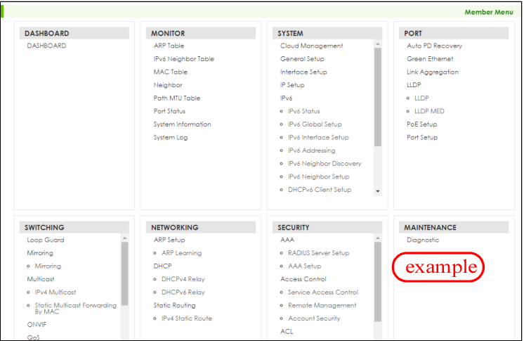
Uploading Firmware to a Cluster Member Switch
You can use FTP to upload firmware to a cluster member switch through the cluster manager switch as shown in the following example.
Example: Uploading Firmware to a Cluster Member Switch
C:\>ftp 192.168.1.1 Connected to 192.168.1.1. 220 Switch FTP version 1.0 ready at Thu Jan 1 00:58:46 1970 User (192.168.0.1:(none)): admin 331 Enter PASS command Password: 230 Logged in ftp> ls 200 Port command okay 150 Opening data connection for LIST --w--w--w- 1 owner group 3042210 Jul 01 12:00 ras -rw-rw-rw- 1 owner group 393216 Jul 01 12:00 config --w--w--w- 1 owner group 0 Jul 01 12:00 fw-00-a0-c5-01-23-46 -rw-rw-rw- 1 owner group 0 Jul 01 12:00 config-00-a0-c5-01-23-46 226 File sent OK ftp: 297 bytes received in 0.00Seconds 297000.00Kbytes/sec. ftp> bin 200 Type I OK ftp> put 470ACAQ0.bin fw-00-a0-c5-01-23-46 200 Port command okay 150 Opening data connection for STOR fw-00-a0-c5-01-23-46 226 File received OK ftp: 262144 bytes sent in 0.63Seconds 415.44Kbytes/sec. ftp> |
The following table explains some of the FTP parameters.
FTP Parameter | Description |
|---|---|
User | Enter “admin”. |
Password | The Web Configurator password default is 1234. |
ls | Enter this command to list the name of cluster member switch’s firmware and configuration file. |
470ACAQ0.bin | This is the name of the firmware file you want to upload to the cluster member switch. |
fw-00-a0-c5-01-23-46 | This is the cluster member switch’s firmware name as seen in the cluster manager switch. |
config-00-a0-c5-01-23-46 | This is the cluster member switch’s configuration file name as seen in the cluster manager switch. |
Restore Configuration
Use this screen to restore a previously saved configuration file (See Backup Configuration for more information on how to back up a configuration file) from your computer to the Switch.
Click MAINTENANCE > Configuration > Restore Configuration to access this screen.
MAINTENANCE > Configuration > Restore Configuration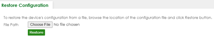
1 Click Choose File or Browse to locate the configuration file you wish to restore.
2 After you have specified the file, click Restore.
The Switch will run on the restored configuration after the restore process.
Configuration Restoring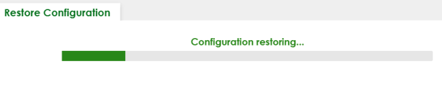
Backup Configuration
Backing up your Switch configurations allows you to create various “snap shots” of your device from which you may restore at a later date. Use this screen to back up your current Switch configuration to a computer.
To access this screen, click MAINTENANCE > Configuration > Backup Configuration in the navigation panel.
MAINTENANCE > Configuration > Backup Configuration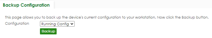
Follow the steps below to back up the current Switch configuration to your computer in this screen.
1 Select which Switch configuration file you want to download to your computer.
2 Click Backup.
3 If the current configuration file is open and/or downloaded to your computer automatically, you can click File > Save As on your computer to save the file to a specific place.
If a dialog box pops up asking whether you want to open or save the file, click Save or Save File to download it to the default downloads folder on your computer. If a Save As screen displays after you click Save or Save File, choose a location to save the file on your computer from the Save in drop-down list box and type a descriptive name for it in the File name list box. Click Save to save the configuration file to your computer.
Erase Running-Configuration
Follow the steps below to remove the running configuration on the Switch. Unlike when you reset the Switch to the factory defaults, the user name, password, system logs, memory logs, baud rate and SSH service are not removed.
To access this screen, click MAINTENANCE > Configuration > Erase Running Configuration in the navigation panel.
1 In the Erase Running Configuration screen, click the Erase button to clear all Switch configuration information you configured and return to the Zyxel default configuration settings.
MAINTENANCE > Configuration > Erase Running Configuration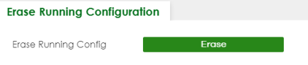
2 Click YES to remove the running configuration on the Switch.
Erase Running Configuration: Confirmation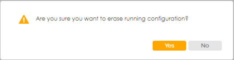
3 In the Web Configurator, click the Save button in the top of the screen to make the changes take effect. If you want to access the Switch Web Configurator again, you may need to change the IP address of your computer to be in the same subnet as that of the default Switch IP address (192.168.1.1 or DHCP-assigned IP).
Save Configuration
To access this screen, click MAINTENANCE > Configuration > Save Configuration in the navigation panel.
Click Config 1 to save the current configuration settings permanently to Configuration 1 on the Switch. These configurations are set up according to your network environment.
Click Config 2 to save the current configuration settings permanently to Configuration 2 on the Switch. These configurations are set up according to your network environment.
Click Custom Default to save the current configuration settings permanently to a customized default file on the Switch. If configuration changes cause the Switch to behave abnormally, click Custom Default (in the MAINTENANCE > Reboot System screen) to have the Switch automatically reboot and restore the saved Custom Default configuration file.
MAINTENANCE > Configuration > Save Configuration 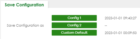
MAINTENANCE > Configuration > Save Configuration (Cloud Mode)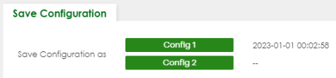
Alternatively, click Save on the top right in any screen to save the configuration changes to the current configuration.
Configure Clone
Cloning allows you to copy the basic and advanced settings from a source port to a destination port or ports. Click MAINTENANCE > Configuration > Configure Clone to open the following screen.
MAINTENANCE > Configuration > Configure Clone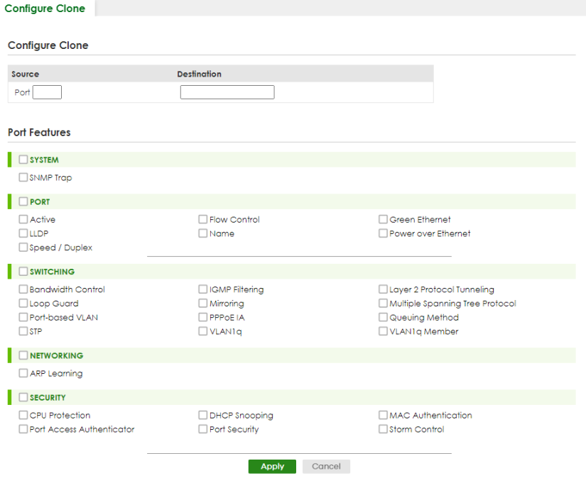
MAINTENANCE > Configuration > Configure Clone (Cloud Mode)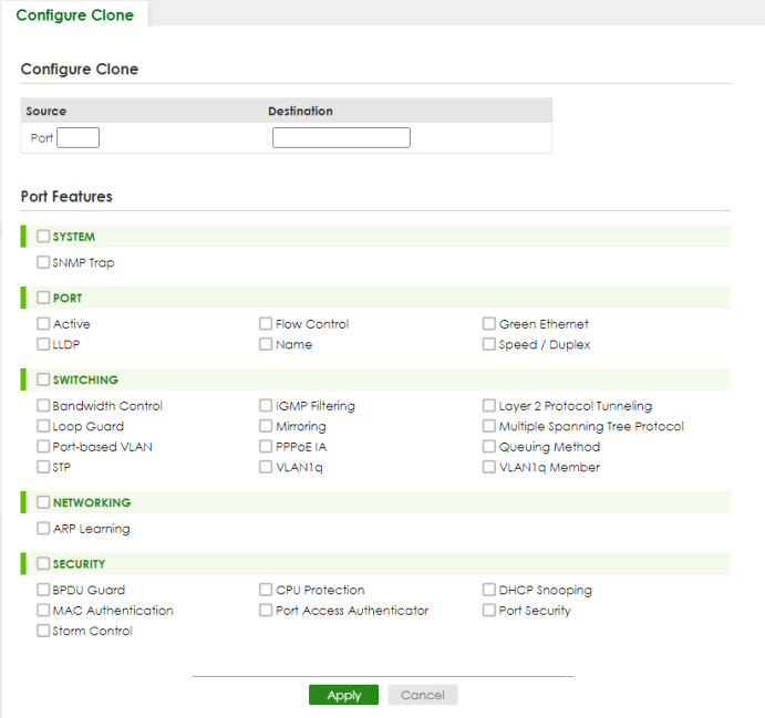
The following table describes the labels in this screen.
label | Description |
|---|---|
Configure Clone | |
Source/Destination Port | Enter the source port under the Source label. This port’s attributes are copied. Enter the destination port or ports under the Destination label. These are the ports which are going to have the same attributes as the source port. You can enter individual ports separated by a comma or a range of ports by using a dash. Example: 2, 4, 6 indicates that ports 2, 4 and 6 are the destination ports. 2-6 indicates that ports 2 through 6 are the destination ports. |
Port Features | |
Select a feature’s checkbox to select a specific feature. Otherwise, select the checkbox in the table heading row to select all features for a category. | |
SYSTEM | Select the system feature (you configured in the SYSTEM menus) to be copied to the destination ports. Otherwise, select the SYSTEM checkbox in the table heading row to select all features for a category. |
PORT | Select which port features (you configured in the PORT menus) should be copied to the destination ports. Otherwise, select the PORT checkbox in the table heading row to select all features for a category. |
SWITCHING | Select which switching features (you configured in the SWITCHING menus) should be copied to the destination ports. Otherwise, select the SWITCHING checkbox in the table heading row to select all features for a category. |
NETWORKING | Select the networking feature (you configured in the NETWORKING menus) to be copied to the destination ports. Otherwise, select the NETWORKING checkbox in the table heading row to select all features for a category. |
SECURITY | Select which security features (you configured in the SECURITY menus) should be copied to the destination ports. Otherwise, select the SECURITY checkbox in the table heading row to select all features for a category. |
Apply | Click Apply to save your changes to the Switch’s run-time memory. The Switch loses these changes if it is turned off or loses power, so use the Save link on the top navigation panel to save your changes to the non-volatile memory when you are done configuring. |
Cancel | Click Cancel to begin configuring this screen afresh. |
Diagnostic
Click MAINTENANCE > Diagnostic in the navigation panel to open this screen. Use this screen to ping IP addresses, run a traceroute, perform port tests or show the Switch’s location between devices.
MAINTENANCE > Diagnostic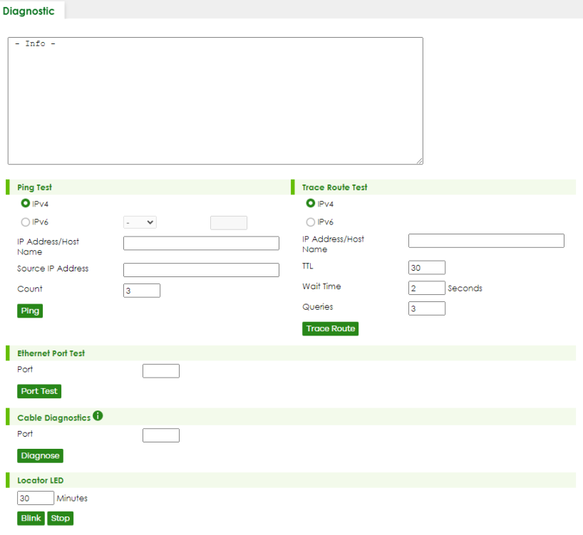
The following table describes the labels in this screen.
LABEL | DESCRIPTION |
|---|---|
Ping Test | |
IPv4 | Select this option if you want to ping an IPv4 address. Otherwise, select – to send ping requests to all VLANs on the Switch. |
IPv6 | Select this option if you want to ping an IPv6 address. You can also select vlan and specify the ID number of the VLAN to which the Switch is to send ping requests. Otherwise, select – to send ping requests to all VLANs on the Switch. |
IP Address/Host Name | Type the IP address or host name of a device that you want to ping in order to test a connection. Click Ping to have the Switch ping the IP address. |
Source IP Address | Type the source IP address that you want to ping in order to test a connection. Click Ping to have the Switch ping the IP address. |
Count | Enter the number of ICMP Echo Request (ping) messages the Switch continuously sends. |
Trace Route Test | |
IPv4 | Select this option if you want to trace the route packets taken to a device with an IPv4 address. Otherwise, select – to trace the path on any VLAN. |
IPv6 | Select this option if you want to trace the route packets taken to a device with an IPv6 address. |
IP Address/Host Name | Enter the IP address or host name of a device to which you want to perform a traceroute. Click Trace Route to have the Switch perform the traceroute function. This determines the path a packet takes to the specified device. |
TTL | Enter the Time To Live (TTL) value for the ICMP Echo Request packets. This is to set the maximum number of the hops (routers) a packet can travel through. Each router along the path will decrement the TTL value by one and forward the packets. When the TTL value becomes zero and the destination is not found, the router drops the packets and informs the sender. |
Wait Time | Specify how many seconds the Switch waits for a response to a probe before running another traceroute. |
Queries | Specify how many times the Switch performs the traceroute function. |
Ethernet Port Test | |
Port | Enter a port number and click Port Test to perform an internal loopback test. |
Cable Diagnostics | |
Port | Enter an Ethernet port number and click Diagnose to perform a physical wire-pair test of the Ethernet connections on the specified ports. The following fields display when you diagnose a port. |
Locator LED | |
Enter a time interval (in minutes) and click Blink to show the actual location of the Switch between several devices in a rack. The default time interval is 30 minutes. Click Stop to have the Switch terminate the blinking locater LED. | |
Firmware Upgrade
You can upgrade the Switch’s firmware through Web Configurator or NCC.
Firmware Upgrade Through NCC
In cloud management mode, NCC will first check if the firmware on the Switch needs to be upgraded. If it does, the Switch will upgrade the firmware immediately. If the firmware does not need to be upgraded, but there is newer firmware available for the Switch, then it will be upgraded according to the firmware upgrade schedule for the Switch on the NCC.
On the NCC web portal, go to Site-wide > Configure > Firmware management to schedule the firmware upgrade time.
Firmware Upgrade Through the Web Configurator
Use the following screen to upgrade your Switch to the latest firmware. The Switch supports dual firmware images, Firmware 1 and Firmware 2. Use this screen to specify which image is updated when firmware is uploaded using the Web Configurator and to specify which image is loaded when the Switch starts up.
Click MAINTENANCE > Firmware Upgrade to view the screen as shown next.
MAINTENANCE > Firmware Upgrade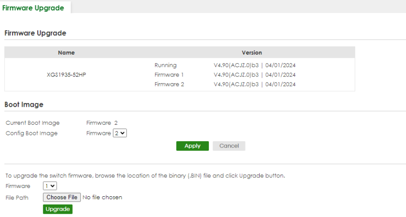
The top of the screen shows which firmware version is currently Running on the Switch. Click Choose File or Browse to locate the firmware file you wish to upload to the Switch in the File Path field. Click Upgrade to load the new firmware. The Switch does not apply the uploaded firmware immediately. Firmware upgrades are only applied after you reboot the Switch using the uploaded firmware.
Click the Config Boot Image drop-down list box to select the boot image (Firmware1 or Firmware2) you want the Switch to use when rebooting, click Apply. Restart the Switch (manually or using the MAINTENANCE > Reboot System screen) to apply the firmware image you selected.
After the process is complete, see the DASHBOARD screen to verify your current firmware version number.
label | description |
|---|---|
Name | This is the name of the Switch that you are configuring. |
Version | The Switch has 2 firmware sets, Firmware 1 and Firmware 2, residing in flash. • Running shows the version number (and model code) and MM/DD/YYYY creation date of the firmware currently in use on the Switch (Firmware 1 or Firmware 2). The firmware information is also displayed at System Information in Basic Setting. • Firmware 1 shows its version number (and model code) and MM/DD/YYYY creation date. • Firmware 2 shows its version number (and model code) and MM/DD/YYYY creation date. |
Boot Image | |
Current Boot Image | This displays which firmware is currently in use on the Switch (Firmware 1 or Firmware 2). |
Config Boot Image | Select which firmware (Firmware 1 or Firmware 2) should load, click Apply and reboot the Switch to see changes, you will also see changes in the Current Boot Image field above as well. |
Apply | Click Apply to save your changes to the Switch’s run-time memory. The Switch loses these changes if it is turned off or loses power, so use the Save link on the top navigation panel to save your changes to the non-volatile memory when you are done configuring. |
Cancel | Click Cancel to begin configuring this screen afresh. |
Firmware | Choose to upload the new firmware to (Firmware) 1 or (Firmware) 2. |
File Path | Click Choose File or Browse to locate the firmware file you wish to upload to the Switch. |
Upgrade | Click Upgrade to load the new firmware. Firmwares are only applied after a reboot. To reboot, go to MAINTENANCE > Reboot System and click Config 1, Config 2 or Factory Default (Config 1, Config 2, Factory Default, and Custom Default are the configuration files you want the Switch to use when it restarts). |
Reboot System
Reboot System allows you to restart the Switch without physically turning the power off. It also allows you to load configuration one (Config 1), configuration two (Config 2), a Custom Default or the Factory Default configuration when you reboot. Follow the steps below to reboot the Switch.
Click MAINTENANCE > Reboot System to view the screen as shown next.
MAINTENANCE > Reboot System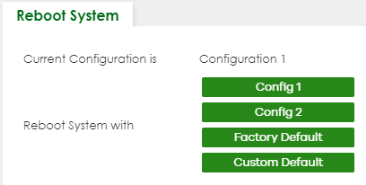
MAINTENANCE > Reboot System (Cloud Mode)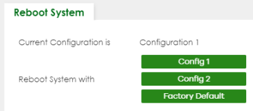
1 Click the Config 1, Config 2, Factory Default, or Custom Default button to reboot and load that configuration file. The confirmation screen displays.
Reboot Confirmation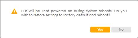
2 Click YES and then wait for the Switch to restart. This takes up to 2 minutes.
Click Config 1 and follow steps 1 to 2 to reboot and load configuration one on the Switch.
Click Config 2 and follow steps 1 to 2 to reboot and load configuration two on the Switch.
Click Factory Default and follow steps 1 to 2 to reboot and load Zyxel factory default configuration settings on the Switch.
Click Custom Default and follow steps 1 to 2 to reboot and load a customized default file on the Switch. This will save the custom default configuration settings to both Configuration 1 and Configuration 2.
SSH Authorized Keys
The Switch can use SSH-authorized keys to authenticate secure SSH connections between a client computer and the Switch (also called the server) without needing a password to connect to the Switch. You can use a third-party utility to generate a private and public key for SSH, for example:
• In Windows, use the PuTTY terminal emulator
• In Linux Ubuntu, use the “ssh-keygen” command.
The Switch and the client computer should have a unique set of private and public keys for encryption/decryption. See SSH Overview for more information about SSH.
Click MAINTENANCE > SSH Authorized Keys to open the following screen. Use this screen to import the client computer’s public key into the Switch.
MAINTENANCE > SSH Authorized Keys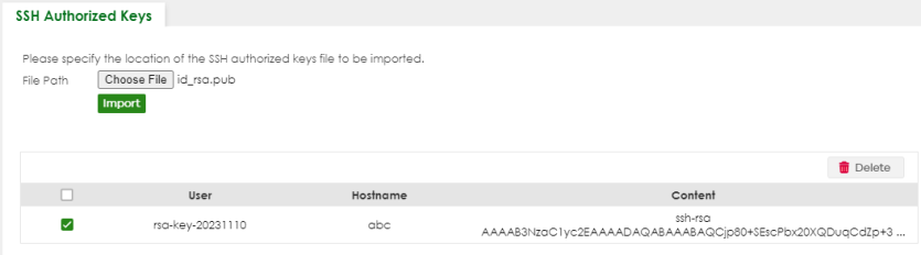
The following table describes the labels in this screen.
label | description |
|---|---|
File Path | Click Choose File or Browse to find the authorized key file you want to upload. |
Import | Click this button to save the authorized key file you want to import from your computer to the Switch. |
Select an entry’s checkbox to select a specific key. | |
User | This field displays the user name of the authorized key file (up to 32 characters). |
Hostname | This field displays the hostname of the authorized key file (up to 32 characters only). |
Content | This field displays the actual encryption key’s text string (up to 64 characters). |
Delete | After selecting an entry’s checkbox, click this button to delete the authorized key file. |
You must install an SSH client program on a client computer (Windows or Linux operating system) to connect to the Switch over SSH.
Example – Generate the SSH Authorized Keys on Windows
PuTTY is a free and open-source terminal emulator. It supports the SSH network protocol. To generate the SSH-authorized keys in PuTTY, the following are the steps at the time of writing:
1 Run PuTTYgen.
2 Select RSA in the Type of key to generate. RSA (Rivest-Shamir-Adleman) is an asymmetric encryption scheme that generates its keys by multiplying two pseudo-random prime numbers. Enter 2048 in the Number of bits in a generated key. SSH keys with encryption lower than 2048 are considered insecure. Then click Generate.
3 Move the mouse back and forth over the blank area to complete the key generation.
4 (Optional) The Key passphrase and Confirm passphrase fields allow you to set a passphrase for your key. Use the passphrase to encrypt the key on your computer. When set, you need to enter the passphrase to use the key. See step 5 on Run PuTTY for SSH Connections on Windows for more information.
5 Click Save public key and Save private key to save the generated keys in your computer.
6 Copy the text on the generated public key into a text editor app like Notepad.
7 At the end of the text string, enter “@(Hostname)”. This will appear in the Hostname field in the MAINTENANCE > SSH Authorized Keys screen. Press Enter to add a line break, then save the text file. Import the text file into the Switch using the SSH Authorized Keys screen.
Run PuTTY for SSH Connections on Windows
To use PuTTY to connect to the Switch through SSH, the following are the steps at the time of writing:
1 Run PuTTY. In the Session screen, enter the IP address of the Switch and “22” for the Port. Select SSH for the Connection type.
2 In the Data screen, enter admin for Auto-login username. The Switch only supports the admin login for the SSH-authorized key.
3 In the Credentials screen, click Browse to locate the generated private key.
4 In the Session screen, you can save the PuTTY configuration by entering a name (for example, “Sample”) in the Saved Sessions, then click Save. Click Open to start the SSH connection.
5 Enter the Passphrase for key if you configured the Key passphrase in step 4 of using the PuTTY Key Generator.
You have now logged in to the Switch.
Example – Generate the SSH Authorized Keys on Linux
To generate the SSH-authorized keys in Ubuntu, enter the following commands at the time of writing:
UserA@UbuntuClient:~$ ssh-keygen –t rsa –b 2048 .........(enter..) UserA@UbuntuClient:~$ ls –all .ssh/ ......... -rw------- 1 UserA UserA 1831 Mar 25 09:46 id_rsa -rw-r--r-- 1 UserA UserA 408 Mar 25 09:46 id_rsa.pub ......... |
“id_rsa” is the private key and “id_rsa.pub” is the public key generated in Ubuntu.
SSH Host Keys
The Switch uses its SSH host public key (P) to authenticate secure SSH connections from an SSH client (C).
When the Switch receives a connection request from an SSH client, the Switch sends its public key to the SSH client. If it's the first time the SSH client accesses the Switch, the SSH client may receive a warning message prompting it to accept or reject the public key.
After the SSH client accepts the Switch's public key, the SSH client encrypts the SSH client's username and password with the Switch's public key and sends the encrypted credentials to the Switch.
When the Switch gets the encrypted credentials from the SSH client, the Switch uses its private key to decrypt the encrypted credentials from the SSH client. If the credentials are correct, the Switch authenticates the SSH client and the SSH client can log into the Switch using SSH.
SSH Host Keys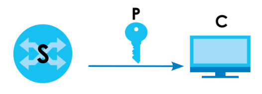
Click MAINTENANCE > SSH Host Keys to open the following screen. Use this screen to regenerate the Switch's SSH host key. You may want to do this to change the factory default SSH host key.
MAINTENANCE > SSH Host Keys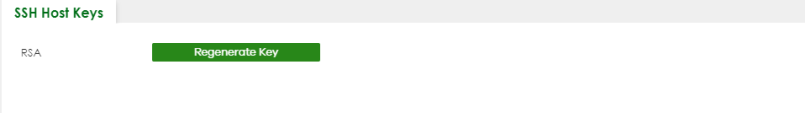
The following table describes the labels in this screen.
label | description |
|---|---|
RSA | At the time of writing, the Switch supports RSA encryption for the SSH host key. See SSH Authorized Keys for information about the RSA. |
Regenerate Key | Click this button to regenerate the Switch's default host key. |
Tech-Support
The Tech-Support feature is a log enhancement tool that logs useful information such as CPU utilization history, memory and Mbuf (Memory Buffer) log and crash reports for issue analysis by customer support should you have difficulty with your Switch. The Tech Support menu eases your effort in obtaining reports and it is also available in CLI command by entering the “Show tech-support” command.
Click MAINTENANCE > Tech-Support to see the following screen.
MAINTENANCE > Tech-Support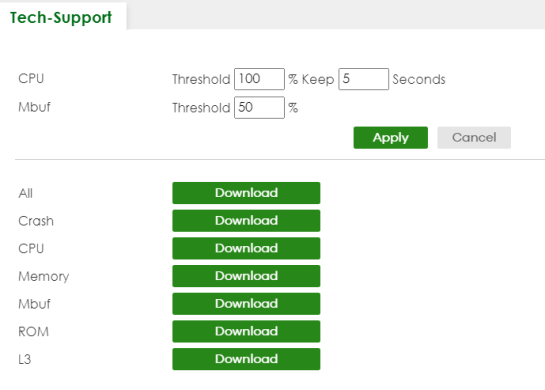
You may need WordPad or similar software to see the log report correctly. The table below describes the fields in the above screen.
Label | description |
|---|---|
CPU | Type a number ranging from 50 to 100 in the CPU threshold box, and type another number ranging from 5 to 60 in the seconds box then click Apply. For example, 80 for CPU threshold and 5 for seconds means a log will be created when CPU utilization reaches over 80% and lasts for 5 seconds. The log report holds 7 days of CPU log data and is stored in volatile memory (RAM). The data is lost if the Switch is turned off or in event of power outage. After 7 days, the logs wrap around and new ones and replace the earliest ones. The higher the CPU threshold number, the fewer logs will be created, and the less data technical support will have to analyze and vice versa. |
Mbuf | Type a number ranging from 50 to 100 in the Mbuf (Memory Buffer) threshold box. The Mbuf log report is stored in flash (permanent) memory. For example, Mbuf 50 means a log will be created when the Mbuf utilization is over 50%. The higher the Mbuf threshold number, the fewer logs will be created, and the less data technical support will have to analyze and vice versa. |
Apply | Click Apply to save your changes to the Switch’s run-time memory. The Switch loses these changes if it is turned off or loses power, so use the Save link on the top navigation panel to save your changes to the non-volatile memory when you are done configuring. |
Cancel | Click Cancel to begin configuring this screen afresh. |
All | Click Download to see all the log report and system status. This log report is stored in flash memory. If the All log report is too large, you can download the log reports separately below. |
Crash | Click Download to see the crash log report. The log will include information of the last crash and is stored in flash memory. |
CPU | Click Download to see the CPU history log report. The 7-days log is stored in RAM and you will need to save it, otherwise it will be lost when the Switch is shutdown or during power outage. |
Memory | Click Download to see the memory section log report. This log report is stored in flash memory. |
Mbuf | Click Download to see the Mbuf (Memory Buffer) log report. This log report is stored in flash memory. |
ROM | Click Download to see the Read Only Memory (ROM) log report. This report is stored in flash memory. |
L3 | Click Download to see the layer-3 Switch log report. The log only applies to the layer-3 Switch models. This report is stored in flash memory. |
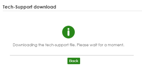
Tech-Support Download
When you click Download to save your current Switch configuration to a computer, the following screen appears. When the log report has downloaded successfully, click Back to return to the previous screen.
MAINTENANCE > Tech-Support: Download