Access Point
Overview
This chapter discusses the menus that you can use to monitor the Nebula-managed APs (Access Points) in your network and configure settings even before an AP is deployed and added to the site.
Nebula Device refers to Zyxel Hybrid APs (NAP / NWA / WAC / WAX Series) in this chapter. To view the list of Nebula Devices that can be managed through NCC, go to Help > Device function table.
Nebula Smart Mesh
Nebula Smart Mesh, also called Smart Mesh or AP Smart Mesh, is a WiFi mesh solution for Nebula Devices. With Smart Mesh, you can have two or more Nebula Devices automatically create a mesh network within your home or office, ensuring there are no areas with a weak wireless signal.
Nebula Smart Mesh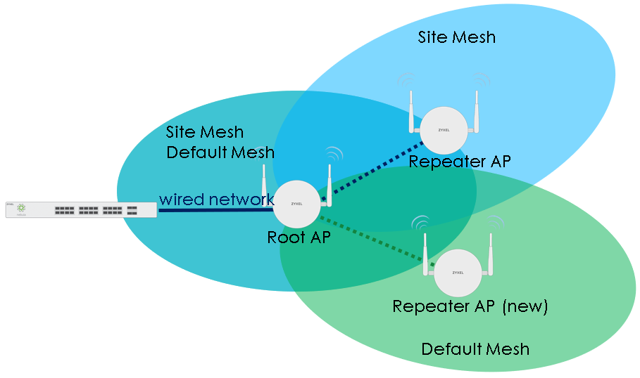
Smart Mesh assigns a role to each Nebula Device depending on its connection method.
• Root AP: A Nebula Device that is connected to the network by Ethernet and can reach the gateway device.
• Repeater AP: A Nebula Device that is connected to the network wirelessly, or that is connected to the network by Ethernet but cannot reach the gateway device.
The Repeater Nebula Devices rebroadcast the root Nebula Device’s SSID, and then relay wireless traffic back to the gateway.
To create a Smart Mesh network, add two or more Nebula Devices to the same Nebula-managed site and ensure that each Nebula Device has Smart Mesh enabled. Then connect one or more Nebula Devices to your network’s gateway using an Ethernet cable, so that you have at least one root Nebula Device. Finally, place one or more non-wired Nebula Devices in areas where you want to extend wireless coverage.
Smart Mesh Network Topology
After you add a Nebula Device to an NCC site and then turn it on, the new Nebula Device automatically connects to a mesh network called the default mesh. The Nebula Device then tries to connect to a root Nebula Device and contact NCC. After the Nebula Device successfully contacts NCC and joins the site, the Nebula Device stops using the default mesh and instead connects to other Nebula Devices in the site using a dedicated network called the site mesh.
Smart Mesh Wireless Hops
Each repeater Nebula Device tries to connect to the site gateway through a root Nebula Device. If a repeater Nebula Device cannot connect directly to a root Nebula Device, then the repeater Nebula Device relays its wireless traffic through another repeater Nebula Device. Each time traffic passes through a wireless connection in the mesh network, it counts as one hop.
Nebula Smart Mesh supports an unlimited number of hops. However, each hop in a mesh network reduces network throughput by up to half. Therefore, we recommend only allowing a maximum of two hops within your Smart Mesh network.
Nebula Smart Mesh Wireless Hops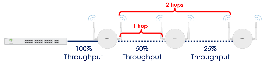
Wireless Bridge
Wireless bridge is a Smart Mesh feature that allows two Nebula Devices to automatically connect two network segments together over a wireless connection. This is useful when you want to extend your wired network to a new area, but it is difficult to run cables to that area.
To use wireless bridge, enable Wireless Bridge on two Nebula Devices in NCC. Then connect wired clients to one of the Nebula Device’s LAN port. These wired clients form a new network segment and are able to reach the site gateway through the Nebula Device’s wireless connection.
Nebula Smart Mesh Wireless Bridge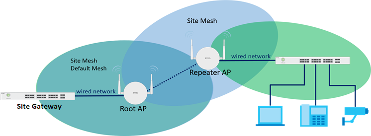
Monitor
Use the Monitor menus to check Nebula Device information, client information, event log messages and summary report for Nebula Devices in the selected site.
Access Points
This screen allows you to view the detailed information about an Nebula Device in the selected site. Click Access Point > Monitor > Access points to access this screen.
Access Point > Monitor > Access Points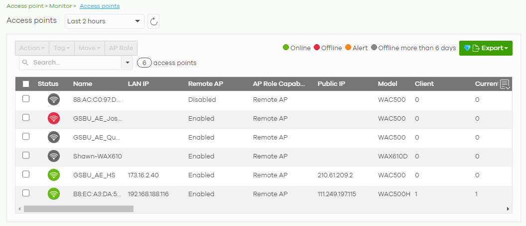
The following table describes the labels in this screen.
Label | Description |
|---|---|
Access point | Select to view device information and connection status in the past two hours, day, week or month. |
Click this button to reload the data-related frames on this page. | |
Action | Perform an action on the selected Nebula Devices. |
Reboot | Select this to restart the Nebula Device. |
Upgrade | Select this to upgrade the firmware on the Nebula Device. |
Tag | Select one or multiple Nebula Devices and click this button to create a new tag for the Nebula Devices or delete an existing tag. At the time of writing, there are two pre-defined tags. The LED tags have priority over the LED setting in the Site-Wide > General Setting screen. • LED_Off: this tag allows you to turn off the LEDs (except the locator LED) on the selected Nebula Devices. • LED_On: this tag allows you to have the LEDs stay lit after the selected Nebula Devices are ready. |
Move | Select one or multiple Nebula Devices and click this button to move the Nebula Devices to another site or remove the Nebula Devices from the current site. |
AP Role | Select one or multiple Nebula Devices and click this button to enable or disable the Remote AP feature. Remote Nebula Device enables the site’s Security Gateway to connect to the Nebula Device through a secure VPN tunnel. This allows you to set up VPN-enabled WiFi Nebula Devices in remote locations, such as in a branch office or at home. Clients connected to these Nebula Devices can securely access your network through the VPN tunnel. |
Search | Specify your desired filter criteria to filter the list of Nebula Devices. |
access points | This shows the number of Nebula Devices connected to the site network. |
Export | Click this button to save the AP list as a CSV or XML file to your computer. |
Status | This shows the status of the Nebula Device. • Green: The Nebula Device is online and has no alerts. • Amber: The Nebula Device has alerts. • Red: The Nebula Device is offline. • Gray: The Nebula Device has been offline for 7 days or more. • For example, an alert is created and the status color is amber when the Nebula Device is transmitting data at 100 Mbps in full duplex mode or when the Nebula Device is in a Limited Power mode. |
Name | This shows the descriptive name of the Nebula Device. |
LAN IP | This shows the local (LAN) IP address of the Nebula Device. |
Remote AP | This shows whether the Remote Nebula Device function is Enabled or Disabled. |
AP Role Capability | This displays whether the Nebula Device can act as a remote Nebula Device (Remote AP) or not (Standard AP). |
Public IP | This shows the global (WAN) IP address of the Nebula Device. |
Model | This shows the model number of the Nebula Device. |
Client | This shows how many clients are connected to the Nebula Device within the specified time period. |
Current Client | This shows how many clients are currently connecting to the Nebula Device. |
MAC Address | This shows the MAC address of the Nebula Device. |
Channel | This shows the channel ID the Nebula Device is using. |
Channel Utilization | This shows the percentage of the channel ID usage. |
Usage | This shows the amount of data consumed by the Nebula Device’s clients. |
% Usage | This shows the percentage of the Nebula Device’s data usage. |
Description | This shows the user-specified description for the Nebula Device. |
Tag | This shows the user-specified tag for the Nebula Device. |
Serial Number | This shows the serial number of the Nebula Device. |
Configuration Status | This shows whether the configuration on the Nebula Device is up-to-date. |
Connectivity | This shows the AP connection status. The red time slot indicates the connection to the NCC is down, and the green time slot indicates the connection is up. Move the cursor over a time slot to see the actual date and time when an Nebula Device is connected or disconnected. |
Ethernet 1 | This shows the speed and duplex mode of the Ethernet connection on the Nebula Device’s up-link port. It shows Down if the Nebula Device is connected to a root Nebula Device wirelessly. |
Neighbor Info | This shows the LLDP information received on the up-link port. |
Production Information | This shows the production information of the Nebula Device. |
Hop | This shows the hop count of the Nebula Device. For example, “1” means the Nebula Device is connected to a root Nebula Device directly. “2” means there is another repeater Nebula Device between this Nebula Device and the root Nebula Device. |
Uplink AP | This shows the role and descriptive name of the Nebula Device to which this Nebula Device is connected wirelessly. |
Uplink Signal | Before the slash, this shows the signal strength the uplink Nebula Device (a root Nebula Device or a repeater) receives from this Nebula Device (in repeater mode). After the slash, this shows the signal strength this Nebula Device (in repeater mode) receives from the uplink AP. |
Uplink Tx/Rx Rate | This is the maximum transmission/reception rate of the root Nebula Device or repeater to which the Nebula Device is connected. |
Wireless bridge | This shows whether wireless bridge is enabled on the Nebula Device. For more information about wireless bridge, see Wireless Bridge. |
Uplink | This shows whether the Nebula Device is connected to the gateway through a wired Ethernet connection or wireless connection. |
Power mode | This shows the Nebula Device’s power status. Full – the Nebula Device receives power using a power adapter and/or through a PoE switch/injector using IEEE 802.3at PoE plus. The PoE device that supports IEEE 802.3at PoE Plus can supply power of up to 30W per Ethernet port. Limited – the Nebula Device receives power through a PoE switch/injector using IEEE 802.3af PoE even when it is also connected to a power source using a power adapter. The PoE device that supports IEEE 802.3af PoE can supply power of up to 15.4W per Ethernet port. When the Nebula Device’s power mode is Limited, the Nebula Device throughput decreases and has just one transmitting radio chain. It always shows Full if the Nebula Device does not support power detection. |
Firmware status | This shows whether the firmware installed on the Nebula Device is up-to-date. |
Current version | This shows the firmware version currently installed on the Nebula Device. |
Remote AP VPN | This shows which VPN the Remote Nebula Device tunnel is configured to use. If Remote Nebula Device is disabled, this field shows Disconnected. |
Click this icon to display a greater or lesser number of configuration fields. For faster loading of data, select only the configuration fields listed that do NOT take a long time to fetch data. |
AP Details
Click an Nebula Device entry in the Access Point > Monitor > Access Points screen to display individual Nebula Device statistics.
Access Point > Monitor > Access Points: AP Details Part 1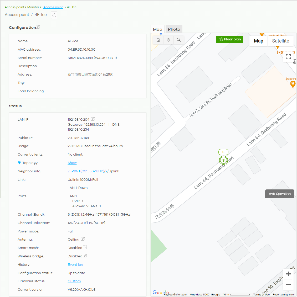
Access Point > Monitor > Access Points: AP Details Part 2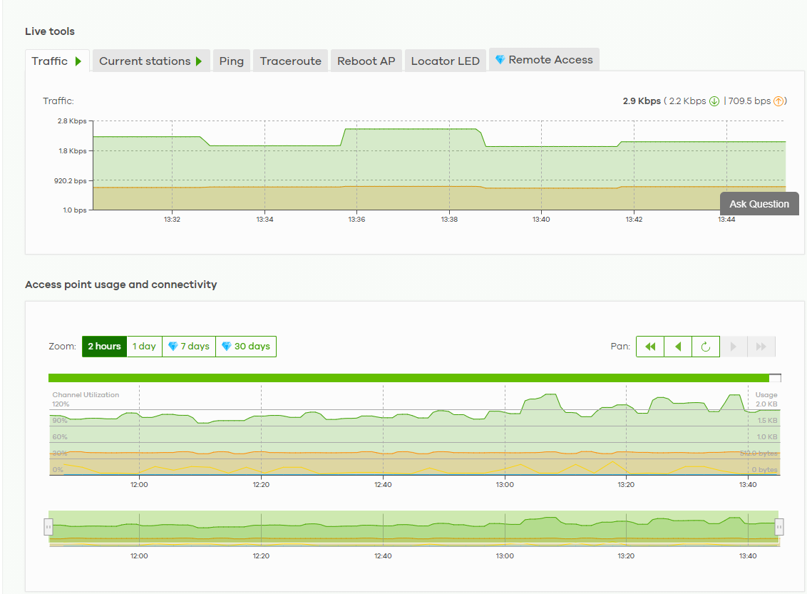
The following table describes the labels in this screen.
Label | Description |
|---|---|
Click this button to reload the data-related frames on this page. | |
Configuration Click the edit configuration icon to change the device name, description, tags and address. You can also move the device to another site. | |
Remote AP | Click this to enable or disable the Remote AP feature. Remote AP enables the site’s Security Gateway to connect to the Nebula Device through a secure VPN tunnel. This allows you to set up VPN-enabled WiFi Nebula Devices in remote locations, such as in a branch office or at home. Clients connected to these Nebula Devices can securely access your network through the VPN tunnel. |
Name | This shows the descriptive name of the Nebula Device. |
MAC Address | This shows the MAC address of the Nebula Device. |
Serial number | This shows the serial number of the Nebula Device. |
Description | This shows the user-specified description for the Nebula Device. |
Address | This shows the user-specified address for the Nebula Device. |
Tag | This shows the user-specified tag for the Nebula Device. |
Load balancing | This shows the load balancing group name that the Nebula Device belongs (up to two groups per AP). Nebula Devices in the same group should be within the proximity. This allows them to share the load. |
Status | |
LAN IP | This shows the local (LAN) IP address of the Nebula Device. It also shows the IP addresses of the gateway and DNS server. Click the edit icon to open a screen where you can change the IP addresses, VLAN ID number and tagging setting. |
Public IP | This shows the global (WAN) IP address of the Nebula Device. |
Usage | This shows the amount of data consumed by the clients. |
Current clients | This shows the number of clients which are currently connecting to the Nebula Device and its details. 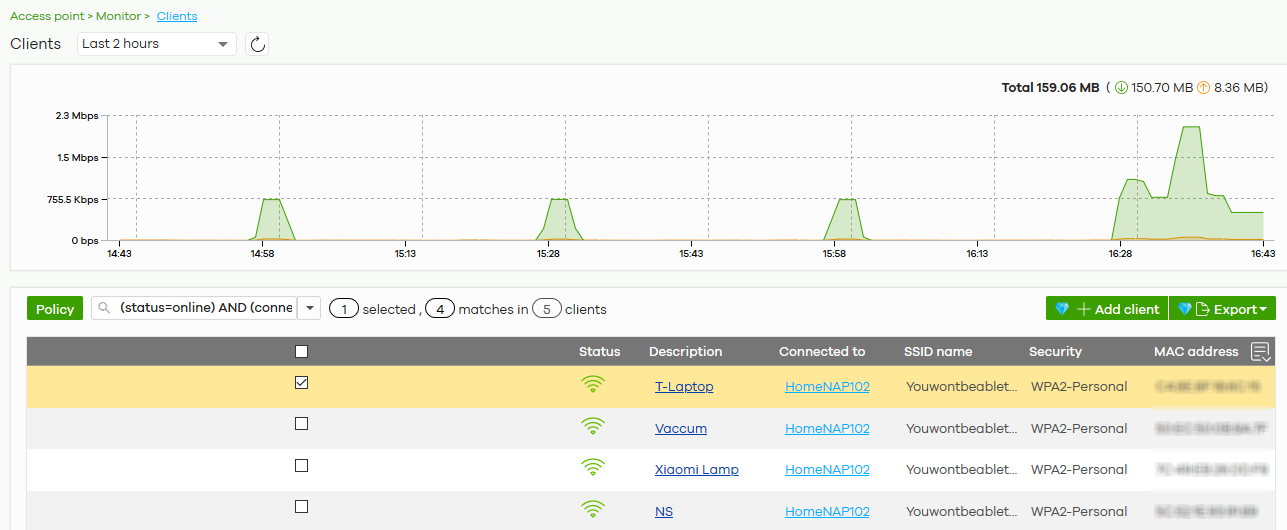 |
Topology | |
Neighbor info | This shows the LLDP information received on the up-link port. |
Link | This shows the speed and duplex mode of the Ethernet connection on the Nebula Device’s ports. It shows Uplink: Wireless if the AP is a repeater and connected to a root Nebula Device wirelessly. A warning icon displays when the Nebula Device is running at 100 Mbps or a lower speed. |
Ports | This is available only for the Nebula Device that has one or more than one Ethernet LAN port (except the uplink port). This shows the PVID of the LAN port and the ID number of VLANs to which the LAN port belongs. See AP & Port Settings for how to change the port’s VLAN settings. |
Storm control | Storm control limits the number of broadcast, multicast and destination lookup failure (DLF) packets received per second on the Nebula Device’s Ethernet ports. When the maximum number of allowable broadcast, multicast and/or DLF packets is reached per second, the subsequent packets are discarded. Enabling this feature reduces broadcast, multicast and/or DLF packets in your network. |
Channel (Band) | This shows the channel ID and WiFi frequency band currently being used by the Nebula Device. |
Channel utilization | This shows the percentage of the channel ID usage. |
Power mode | This shows Full when the Nebula Device receives power directly through a power outlet. This shows Full (Power by DC) when the Nebula Device receives power using a power adapter. This shows Full (Power by PoE) when the Nebula Device receives power through a PoE switch/injector using IEEE 802.3at PoE plus. The PoE device that supports IEEE 802.3at PoE Plus can supply power of up to 30W per Ethernet port. This shows Limited (Require 802.3bt power) when the Nebula Device receives power through a PoE switch/injector using IEEE 802.3bt PoE even when it is also connected to a power source using a power adapter. The PoE device that supports IEEE 802.3bt PoE can supply power of up to 71.3W per Ethernet port. This shows Limited (Require 802.3at power) when the Nebula Device receives power through a PoE switch/injector using IEEE 802.3at PoE even when it is also connected to a power source using a power adapter. The PoE device that supports IEEE 802.3at PoE can supply power of up to 15.4W per Ethernet port. This field is blank when the AP’s firmware is older than version 5.50 or (WAX650S / WAX510D firmware is older than version 6.00P4C0). Or when the AP is offline. Click the edit icon to open a screen where you can enable full power mode. |
Antenna | This displays the antenna orientation settings for the Nebula Device that comes with internal antennas and also has an antenna switch. |
Smart mesh | This shows whether Nebula Smart Mesh is enabled on the Nebula Device. For more information about Smart Mesh, see Nebula Smart Mesh. |
Edit | Edit the Nebula Device’s Smart Mesh settings. |
Enabled | Enable or disable Smart Mesh on the Nebula Device. This setting overrides the Smart Mesh settings configured for the Nebula Device’s site in NCC. |
Lock | When enabled, the Nebula Device’s local Smart Mesh settings overrides the Smart Mesh settings configured for the Nebula Device’s site in NCC. Example 1: If Smart Mesh is enabled for the site in NCC, you can disable Smart Mesh on the Nebula Device by setting Lock to on and Enabled to off. Example 2: If Smart Mesh is disabled for the site in NCC, you can enable Smart Mesh on the Nebula Device by setting Lock to on and Enabled to on. |
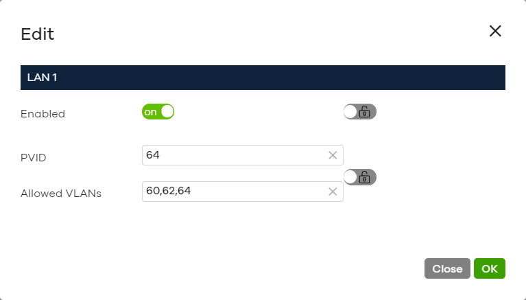
Wireless bridge | This shows whether wireless bridge is enabled on the Nebula Device. For more information about wireless bridge, see Wireless Bridge. |
Edit | Edit the Nebula Device’s wireless bridge settings. |
Enabled | Enable or disable wireless bridge on the Nebula Device. |
Allowed VLANs | Enter the IDs of the VLANs that the Nebula Device will forward over the wireless bridge. By default, this field uses the VLANs allowed for LAN1 at AP > Configure > AP & Port Settings. For details, see AP & Port Settings. |
History | Click Event log to go to the Access Point > Monitor > Event log screen. |
Configuration status | This shows whether the configuration on the Nebula Device is up-to-date. |
Firmware status | This shows whether the firmware on the Nebula Device is up-to-date or there is firmware update available for the Nebula Device. |
Current version | This shows the firmware version currently installed on the Nebula Device. |
Map | This shows the location of the Nebula Device on Google map. |
Photo | This shows the photo of the Nebula Device. Click Add to upload one or more photos. Click x to remove a photo. |
Live tools | |
Traffic | This shows the Nebula Device traffic statistics. |
Current stations | This shows the Nebula Device’s connected wireless clients’ MAC address, SSID name, IPv4 Address, Signal strength, Security, Channel, Tx rate, Rx rate, Association time, and Capability. |
Ping | Enter the domain name or IP address of a computer that you want to perform ping from the Nebula Device in order to test a connection and click Ping. This can be used to determine if the Nebula Device and the computer are able to communicate with each other. |
Traceroute | Enter the domain name or IP address of a computer that you want to perform traceroute from the Nebula Device and click Run. This determines the path a packet takes to the specified computer. |
Reboot AP | Click the Reboot button to restart the Nebula Device. |
Locator LED | Enter a time interval between 1 and 60 minutes. The locator LED will blink for the number of minutes set here once you turn on the Locator LED. Click the  button to turn on the locator feature, which shows the actual location of the Nebula Device between several devices in the network. button to turn on the locator feature, which shows the actual location of the Nebula Device between several devices in the network. |
Remote Access | This allows you to establish a remote connection to this Nebula Device by specifying the port number. Then click Establish. This feature is available to the organization owner, organization administrators with full privileges, and site administrators with full privileges. |
Access point usage and connectivity Move the cursor over the chart to see the transmission rate at a specific time. | |
Zoom | Select to view the statistics in the past 2 hours, day, week, or month. |
Pan | Click to move backward or forward by one day or week. |
Clients
This screen allows you to view the connection status and detailed information about clients connected to an Nebula Device in the selected site. Click Access Point > Monitor > Clients to access this screen.
Access Point > Monitor > Clients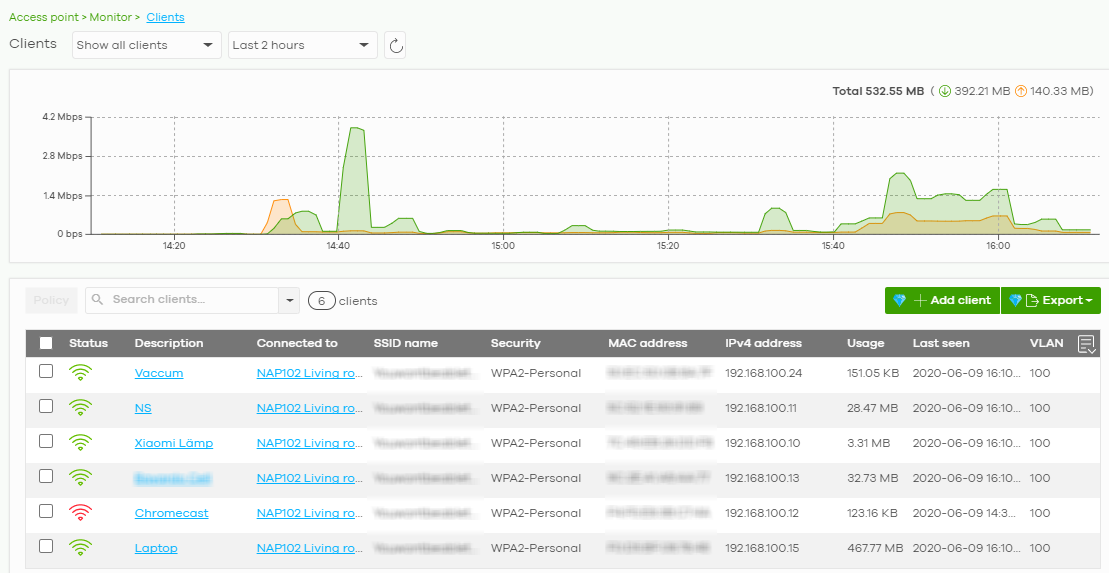
The following table describes the labels in this screen.
Label | Description |
|---|---|
Clients | Select to view the connected device information and connection status in the past two hours, day, week or month. • Select Show all clients to show clients that have been online during the selected time period. • Select Show policy clients to show clients that have a white-listed or blocked policy applied to them, regardless of when they were last online. The client’s usage data is calculated according to the selected time period. |
Click this button to reload the data-related frames on this page. | |
y-axis | The y-axis shows the transmission speed of data sent or received by the client in kilobits per second (Kbps). |
x-axis | The x-axis shows the time period over which the traffic flow occurred. |
Policy | Select the clients from the table below, and then choose the security policy that you want to apply to the selected clients. Choose Normal to apply the captive portal authentication to the selected clients. To allow the selected clients to bypass captive portal authentication, choose Whitelisted. Choose Blocked when the selected clients fails the captive portal authentication. Choose To specific SSID to selectively apply captive portal authentication to specific SSIDs. Then, click Apply policy. 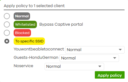 |
Search | Specify your desired filter criteria to filter the list of clients. |
Clients | This shows the number of clients connected to an Nebula Device in the site network. |
Add client | Click this button to open a window where you can specify a client’s name and MAC address to apply a policy before it is connected to the Nebula Device’s network. |
Export | Click this button to save the client list as a CSV or XML file to your computer. |
Status | This shows whether the client is online (green) or offline (red), and whether the client is wired or wireless. |
Description | This shows the descriptive name of the client. Click the name to display the individual client statistics. See Client Details. |
Connected to | This shows the name of the Nebula Device to which the client is connected. Click the name to display the individual Nebula Device statistics. See AP Details. |
SSID Name | This shows the name of the Nebula Device’s wireless network to which the client is connected. |
MAC address | This shows the MAC address of the client. |
IPv4 address | This shows the IP address of the client. |
Channel | This shows the channel ID the client is using. |
Band | This shows the WiFi frequency band currently being used by the client. |
Signal strength | This shows the RSSI (Received Signal Strength Indicator) of the client’s wireless connection, and an icon showing the signal strength. Icon default thresholds: • Green/5 blocks: signal is greater than –67 dBm, strong signal • Amber/4 blocks: signal –67 to –73 dBm, average signal • Amber/3 blocks: signal –74 to –80 dBm, below average signal • Red/2 blocks: signal is less than –80 dBm, weak signal |
Security | This shows which secure encryption method is being used by the client to connect to the Nebula Device. |
Tx Rate | This shows maximum transmission rate of the client. |
Rx Rate | This shows maximum reception rate of the client. |
Download | This shows the amount of data received by the client since it last connected. |
Upload | This shows the amount of data transmitted from the client since it last connected. |
Usage | This shows the amount of data consumed by the AP (upload + download) since it last connected. |
Association time | This shows the date and time the client associated with the Nebula Device. |
First seen | This shows the first date and time the client was discovered. |
Last seen | This shows the last date and time the client was discovered. |
Capability | This shows the WiFi standards supported by the client or the supported standards currently being used by the client. |
Manufacturer | This shows the manufacturer of the client device. |
Authentication | This shows the authentication method used by the client to access the network. This shows Unauthorized if the captive portal page displays but the client has not proceeded with the authentication process. The field is blank if web authentication is disabled. |
User | This shows the user account information used to log into the NCC through captive portal, using Facebook login or 802.1x with Nebula cloud authentication or a RADIUS server. This field is blank if the user logs in through Facebook WiFi or web authentication is disabled. |
OS | This shows the operating system running on the client device. |
Policy | This shows the security policy applied to the client. |
VLAN | This shows the ID number of the VLAN to which the client belongs. |
Note | This shows additional information for the client. |
Click this icon to display a greater or lesser number of configuration fields. |
Client Details
Click a client entry in the Access Point > Monitor > Clients screen to display individual client statistics.
Access Point > Monitor > Clients: Client Details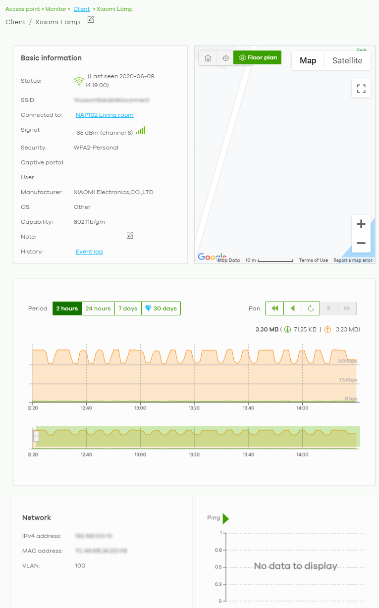
The following table describes the labels in this screen.
Label | Description |
|---|---|
Status | This shows whether the client is online (green), or goes off-line (red). It also shows the last date and time the client was discovered. |
SSID | This shows the name of the Nebula Device’s wireless network to which the client is connected. |
Connected to | This shows the name of the Nebula Device to which the client is connected. Click the name to display the individual Nebula Device statistics. See AP Details. |
Signal | This shows the RSSI (Received Signal Strength Indicator) of the client’s wireless connection, and an icon showing the signal strength. Icon default thresholds: • Green/5 blocks: signal is greater than –67 dBm, strong signal • Amber/4 blocks: signal –67 to –73 dBm, average signal • Amber/3 blocks: signal –74 to –80 dBm, below average signal Red/2 blocks: signal is less than –80 dBm, weak signal |
Security | This shows the encryption method used to connect to the Nebula Device. |
Captive portal | This shows the web authentication method used by the client to access the network. |
User | This shows the number of users currently connected to the network through the client device. |
Manufacturer | This shows the manufacturer of the client device connected to the Nebula Device. |
OS | This shows the operating system running on the client device, if known. |
Capability | This shows the WiFi standards supported by the client or the supported standards currently being used by the client. |
Note | This shows additional information for the client. Click the edit icon to change it. |
History | Click Event log to go to the Access Point > Monitor > Event log screen. |
Map | This shows the location of the client on the Google map. |
Period | Select to view the statistics in the past two hours, day, week or month. |
Pan | Click to move backward or forward by two hours or one day. |
y-axis | The y-axis shows the transmission speed of data sent or received by the client in kilobits per second (Kbps). |
x-axis | The x-axis shows the time period over which the traffic flow occurred. |
Network | |
IPv4 address | This shows the IP address of the client. |
MAC address | This shows the MAC address of the client. If you applied a security policy to a client using the Add client button in the Access Point > Monitor > Clients screen, and the client has never been connected to the Nebula Device’s network, an edit icon appears allowing you to modify the client’s MAC address, |
VLAN | This shows the ID number of the VLAN to which the client belongs. |
Ping | Click the button to ping the client’s IP address from the Nebula Device to test connectivity. |
Loss rate | This shows the rate of packet loss when you perform ping. |
Average latency | This shows the average latency in ms when you perform ping. |
Event Log
Use this screen to view wireless Nebula Device log messages. You can enter the Nebula Device name or a key word, select one or multiple event types, or specify a date/time or even a time range to display only the log messages related to it.
Click Access Point > Monitor > Event Log to access this screen.
Access Point > Monitor > Event log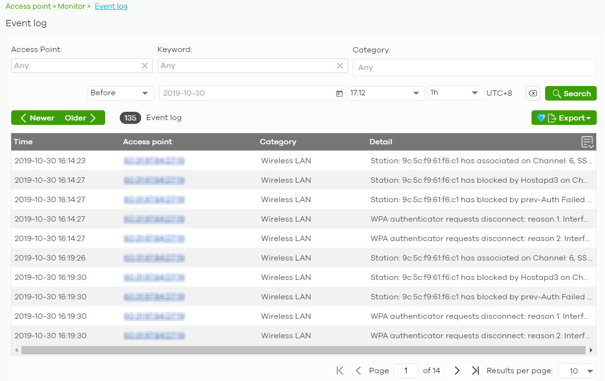
Wireless Health
This screen lets you monitor the health of wireless networks for your Nebula Devices and connected wireless clients.
You can improve wireless network performance by doing the following:
• Enable DCS (Dynamic Channel Selection) to select a radio channel with least interference
• Enable client steering to use a stronger WiFi signal
• Change channel bandwidth to reduce radio interference from other wireless devices
Click Access Point > Monitor > Wireless Health to access this screen.
Access Point > Monitor > Wireless Health
The following table describes the labels in this screen.
Label | Description |
|---|---|
AP wireless health overview Move the cursor over the information icon to view the supported Nebula Device model list. | |
Good/Fair/Poor | This shows the number of supported Nebula Devices that are currently on-line, using the specified frequency band that are in Good, Fair or Poor wireless health threshold as detected by Nebula. |
AP radio health | Select to view the health of all supported Nebula Device wireless networks using the 5 GHz or 2.4 GHz band. You can select to view the health report for the past day, week or month, as well as filter the Nebula Device to view. |
y-axis | The y-axis represents the state of wireless health. |
x-axis | The x-axis shows the time period over which the Nebula Device health state is recorded. |
Top APs by health alert | |
Name | This shows the descriptive name of the Nebula Device. |
Model | This shows the model number of the Nebula Device. |
Alert | This shows how many times the Nebula Device is in a poor state of wireless health. The NCC generates a log when the Nebula Device is in poor wireless health. You can view the log messages in the Access Point > Monitor > Event Log screen. |
5G auto optimization action | Select ON to enable and specify how the Nebula Device improves the wireless network performance. Otherwise, select OFF to disable it. • Adaptive channel width – select this option to have the Nebula Device change the channel bandwidth from 80 MHz to 20 MHz to reduce the radio interference with other wireless devices. • DCS (Dynamic Channel Selection) – select this option to have the Nebula Device scan and choose a radio channel that has least interference. |
2.4G auto optimization action | Select ON to enable and specify how the Nebula Device improves the wireless network performance. Otherwise, select OFF to disable it. • DCS (Dynamic Channel Selection) – select this option to have the Nebula Device scan and choose a radio channel that has least interference. |
Client wireless health overview | |
Good/Fair/Poor | This shows the number of connected wireless clients that are currently on-line, using the specified frequency band and in Good, Fair or Poor wireless health threshold as detected by Nebula. |
Client health | Select to view the health of all wireless clients which are connected to the supported Nebula Devices using the 5 GHz or 2.4 GHz band. You can select to view the health report for the past day, week or month, as well as filter the wireless station to view. |
y-axis | The y-axis represents the state of wireless health. |
x-axis | The x-axis shows the time period over which the client health state is recorded. |
Top clients by health alert | |
Description | This shows the descriptive name of the client. |
Alert | This shows how many times the client is in a poor state of wireless health. The NCC generates a log when the client is in poor wireless health. You can view the log messages in the Access Point > Monitor > Event Log screen. |
Clients auto optimization | Select ON to have the Nebula Device try to steer the wireless clients in poor health to a Nebula Device or SSID with a strong signal. Client steering to improve the signal strength is done every 30 minutes. Otherwise, select OFF to disable steering. |
Summary Report
This screen displays network statistics for Nebula Devices of the selected site, such as bandwidth usage, top clients and/or top SSIDs.
Click Access Point > Monitor > Summary Report to access this screen.
Access Point > Monitor > Summary Report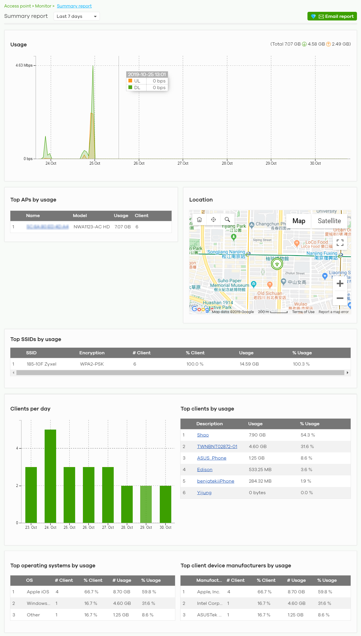
The following table describes the labels in this screen.
Label | Description |
|---|---|
Summary report | Select to view the report for the past day, week or month. Alternatively, select Custom range... to specify a time period the report will span. You can also select the number of results you want to view in a table. |
Email report | Click this button to send summary reports by email, change the report logo and set email schedules. |
Usage | |
y-axis | The y-axis shows the transmission speed of data sent on this port in megabits per second (Mbps). |
x-axis | The x-axis shows the time period over which the traffic flow occurred. |
Top APs by usage | |
# | This shows the ranking of the Nebula Device. |
Name | This shows the descriptive name of the Nebula Device. |
Model | This shows the model number of the Nebula Device. |
Usage | This shows the amount of data transmitted or received by the Nebula Device. |
Client | This shows how many clients are currently connecting to the Nebula Device. |
Location This shows the location of the Nebula APs on the map. | |
Top SSIDs by usage | |
# | This shows the ranking of the SSID. |
SSID | This shows the SSID network name. |
Encryption | This shows the encryption method used by the SSID network. |
# Client | This shows how many WiFi clients are connecting to this SSID. |
% Client | This shows what percentage of associated WiFi clients are connecting to this SSID. |
Usage | This shows the total amount of data transmitted or received by clients connecting to this SSID. |
% Usage | This shows the percentage of usage for the clients connecting to this SSID. |
Clients per day | |
y-axis | The y-axis represents the number of clients. |
x-axis | The x-axis represents the date. |
Top clients by usage | |
# | This shows the ranking of the client. |
Description | This shows the descriptive name or MAC address of the client. |
Usage | This shows the total amount of data transmitted and received by the client. |
% Usage | This shows the percentage of usage for the client. |
Top operating systems by usage | |
# | This shows the ranking of the operating system. |
OS | This shows the operating system of the client device. |
# Client | This shows how many client devices use this operating system. |
% Client | This shows the percentage of top client devices which use this operating system. |
# Usage | This shows the amount of data consumed by the client device on which this operating system is running. |
% Usage | This shows the percentage of usage for top client devices which use this operating system. |
Top client device manufacturers by usage | |
# | This shows the ranking of the manufacturer. |
Manufacturer | This shows the manufacturer name of the client device. |
# Client | This shows how many client devices are made by the manufacturer. |
% Client | This shows the percentage of top client devices which are made by the manufacturer. |
# Usage | This shows the amount of data consumed by the client device. |
% Usage | This shows the percentage of usage for the client device. |
Configure
Use the Configure menus to set the WiFi security settings for Nebula Devices of the selected site.
SSID Overview
This screen allows you to configure up to eight different SSID profiles for your Nebula Devices. An SSID, or Service Set IDentifier, is basically the name of the wireless network to which a wireless client can connect. The SSID appears as readable text to any device capable of scanning for wireless frequencies (such as the WiFi adapter in a laptop), and is displayed as the wireless network name when a person makes a connection to it.
Click Access Point > Configure > SSID overview to access this screen.
Access Point > Configure > SSID overview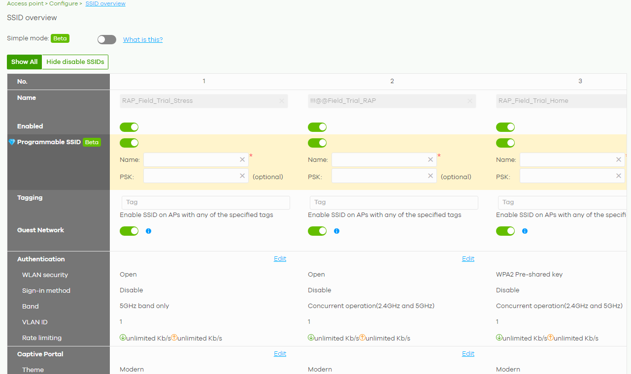
The following table describes the labels in this screen.
Label | Description |
|---|---|
Simple Mode | Select On to enable Simple Mode. Simple Mode allows you to create SSID profiles by only specifying an SSID name and optional password. NCC sets all other wireless settings to default. |
Show All/Hide disabled SSIDs | Select to display all SSID profiles or the active SSID profiles only. |
No. | This shows the index number of this profile. |
Name | This shows the SSID name for this profile. Click the text box and enter a new SSID if you want to change it. |
Enabled | Click to turn on or off this profile. |
Programmable SSID | Select On to have each Nebula Device that uses this SSID generate a unique SSID name and pre-shared key (PSK) based on the Nebula Device’s model name, serial number, or MAC address. For example, a hotel can install an Nebula Device in each room and then have each Nebula Device broadcast a unique SSID based on the room number: FreeWiFi_Room1, FreeWiFi_Room2, FreeWiFi_Room3, and so on. |
Name | Name: Enter a programmable SSID name in the format PREFIX+VALUE(X). This name overrides the original SSID name. • PREFIX: Optional prefix to add to the SSID, for example “FreeWiFi_”. To use “$” in the SSID name, enter “$$” • VALUE: Specify a Nebula Device value to use to generate the SSID name. Use one of the following: $AP = Nebula Device device name. $MAC = Nebula Device MAC address. $SN = Nebula Device serial number. • X: Specify how many characters of the Nebula Device value to use in the SSID. A positive number means the first X characters, and a negative number means the last X characters. Example: FreeWiFi_Room$AP(–3) generates an SSID called “FreeWiFi_Room” + the last three characters of the AP device name. |
PSK | PSK: Enter an optional programmable PSK in the format GENTYPE(Y). • GENTYPE: Specify how the Nebula Device will generate a random PSK. $GENMIX = The Nebula Device generates a mix of random letters and numbers. $GENNUM = The Nebula Device generates a mix of random numbers only. Y = Specify the length of the PSD. The minimum length is 8. Example: $GENNUM(10) generates a unique 10-character PSK for this SSID, consisting only of numbers. |
Tagging | Enter or select the tags you created for Nebula Devices in the Access Point > Monitor > Access Points screen. The SSID profile will only be applied to Nebula Devices with the specified tag. If you leave this field blank, this SSID profile will be applied to all Nebula Devices in the site. |
Guest Network | Select On to set this wireless network as a guest network. Layer 2 isolation and intra-BSS blocking are automatically enabled on the SSID. Wireless clients connecting to this SSID can access the Internet through the Nebula Device but cannot directly connect to the LAN or the wireless clients in the same SSID or any other SSIDs. 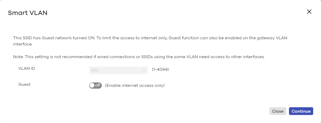 |
Authentication | |
Edit | Click this button to go to the Authentication screen and configure the advanced settings, such as SSID availability, WiFi security, L2 isolation, intra-BSS traffic blocking and walled garden settings. See SSID Settings. |
WLAN security | This shows the encryption method used in this profile. |
Sign-in method | This shows the authentication method used in this profile. |
Band | This shows whether the SSID use either 2.4 GHz band or the 5 GHz band. If it shows Concurrent operation, the SSID uses both frequency bands. |
VLAN ID | This shows the ID number of the VLAN to which the SSID belongs. |
Rate limiting | This shows the maximum incoming/outgoing transmission data rate (in Kbps) on a per-station basis. |
Captive portal | |
Edit | Click this button to go to the Captive Portal screen and configure the captive portal settings. See Captive Portal Customization. |
Theme | If captive portal is enabled, this shows the name of the captive portal page used in this profile. |
SSID Settings
Use this screen to configure the WiFi security, L2 isolation, intra-BSS traffic blocking and walled garden settings for the SSID profiles.
Click Access Point > Configure > SSID settings to access this screen.
Access Point > Configure > SSID settings Part 1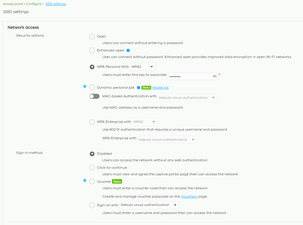
Access Point > Configure > SSID settings Part 2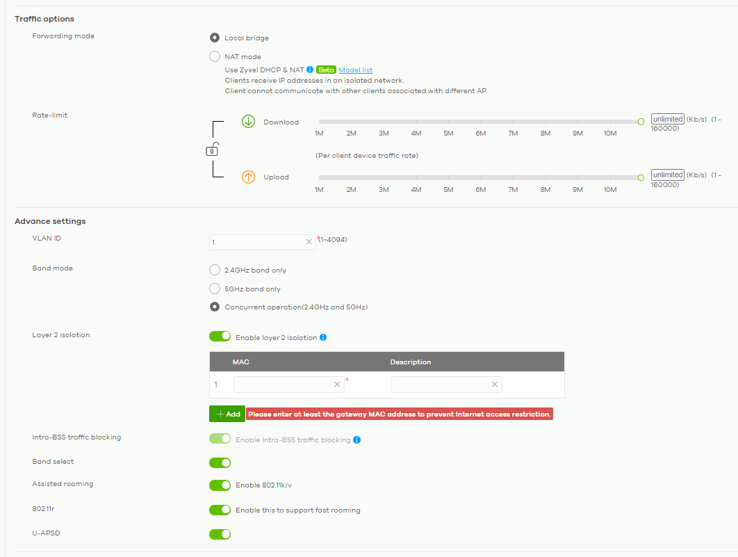
The following table describes the labels in this screen.
Label | Description |
|---|---|
SSID settings | Select the SSID profile to which the settings you configure here is applied. |
Network access | |
Security options | Select Open to allow any client to associate this network without any data encryption or authentication. Select Enhanced-open to allow any client to associate this network without any password but with improved data encryption. Upon selecting Enhanced-open or WPA Personal With WPA3, transition mode generates two VAP so devices that do not support Enhanced-Open/WPA Personal With WPA3 can connect using Open/WPA Personal With WPA2 network. This is always on at the time of writing. Select WPA Personal With (WPA1/WPA2/WPA3) and enter a pre-shared key from 8 to 64 case-sensitive keyboard characters to enable WPA1/2/3-PSK data encryption. Upon selecting WPA Personal With WPA3, Nebula Devices that do not support it will revert to WPA2. • Turn on 802.11r to enable IEEE 802.11r fast roaming on the AP. 802.11r fast roaming reduces the delay when the clients switch from one Nebula Device to another by allowing security keys to be stored on all Nebula Devices in a network. Information from the original association is passed to the new Nebula Device when the client roams. The client does not need to perform the whole 802.1x authentication process. Select Dynamic personal psk to have every user connect to the SSID using a unique pre-shared key (PSK) that is linked to their user account. This allows you to revoke a user’s wireless network access by disabling their account. After enabling this option, you must create one or more DPPSK users in the site or organization at Configure > Cloud authentication > Account Type > DPPSK. • For details on creating a site DPPSK user, see Create/Update User Account. • For details on creating organization DPPSK users, see Cloud Authentication. Turn on MAC-based Authentication with to authenticate wireless clients by their MAC addresses. You can select My RADIUS server to use an external RADIUS server or select Nebula cloud authentication to use the NCC for MAC authentication. Select WPA-Enterprise with to enable 802.1X secure authentication. You can select My RADIUS server to use an external RADIUS server or select Nebula cloud authentication to use the NCC for 802.1X authentication. • Turn on 802.11r to enable IEEE 802.11r fast roaming on the Nebula Device. 802.11r fast roaming reduces the delay when the clients switch from one Nebula Device to another by allowing security keys to be stored on all Nebula Devices in a network. Information from the original association is passed to the new Nebula Device when the client roams. The client does not need to perform the whole 802.1x authentication process. • Select Two-Factor Authentication to require that the user log in using both their password and a Google Authenticator code. To log in, users must have Two-Factor Authentication enabled on their account and have setup Google Authenticator on their mobile device. Select Enable on RAP only to only require Two-Factor Authentication when accessing the network through a remote access point (RAP). |
Sign-in method | Select Disable to turn off web authentication. Select Click-to-continue to block network traffic until a client agrees to the policy of user agreement. Select Voucher to require that a user logs in with a voucher code. For details on vouchers, see Vouchers. Select Sign-on with and: • select Nebula cloud authentication to block network traffic until a client authenticates with the NCC through the specifically designated web portal page. • select My RADIUS server to block network traffic until a client authenticates with an external RADIUS server through the specifically designated web portal page. • select Facebook to block network traffic until a client authenticates with the NCC using Facebook Login. Facebook Login is a secure and quick way for users to log into your app or website using their existing Facebook accounts. If you get the App ID for your app at the Facebook developers site, you can enter your Facebook app ID to obtain more information about your users using Facebook Analytics, such as user activity, age, gender, and so on. • select Facebook Wi-Fi to let users check in to a business on Facebook for free Internet access after connecting to the Nebula Device’s wireless network. Users then have the option to like the Facebook fan page. You should already have set up a Facebook fan page associated with the business location. Click here to open the Facebook WiFi configuration screen in a new window, where you can select the Facebook Page associated with your location and configure bypass mode and session length. 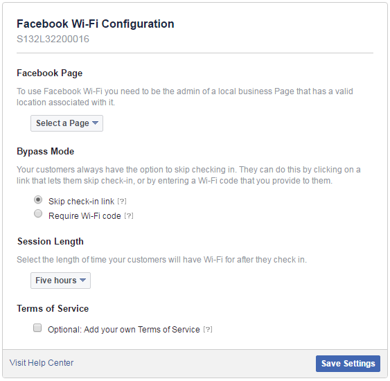 |
RADIUS server | This field is available only when you select to use the following: • MAC-based Authentication with My RADIUS server or WPA2-Enterprise with My RADIUS server in the WLAN security field, or • when you select Sign-on with My RADIUS server in the Sign-in method field. Click Add to specify the IP address/domain name, port number and shared secret password of the RADIUS server to be used for authentication. |
NAS Identifier | If the RADIUS server requires the Nebula Device to provide the Network Access Server identifier attribute with a specific value, enter it here. |
RADIUS accounting | This field is available only when you select to use WPA2-Enterprise with My RADIUS server in the WLAN security field, or when you select Sign-on with My RADIUS server in the Sign-in method field. Select RADIUS accounting enabled to enable user accounting through an external RADIUS server. Select RADIUS accounting disabled to disable user accounting through an external RADIUS server. |
RADIUS accounting servers | If you select RADIUS accounting enabled, click Add to specify the IP address, port number and shared secret password of the RADIUS server to be used for accounting. |
Captive portal advance settings | |
Walled garden | Select On to enable Walled garden. |
Walled garden ranges | This field is not configurable if you set Sign-in method to Disable. With a walled garden, you can define one or more web site addresses that all users can access without logging in. These can be used for advertisements for example. Select to turn on or off the walled garden feature. Specify walled garden web site links, which use a (wildcard) domain name or an IP address for web sites that all users are allowed to access without logging in. |
Self-registration | This field is available only when you set Sign-in method to Sign-on with Nebula Cloud authentication. Select Allow users to create accounts with auto authorized or Allow users to create accounts with manual authorized to display a link in the captive portal login page. The link directs users to a page where they can create an account before they authenticate with the NCC. For Allow users to create accounts with manual authorized, users cannot log in with the account until the account is authorized and granted access. For Allow users to create accounts with auto authorized, users can just use the registered account to log in without administrator approval. Select Don’t allow users to create accounts to not display a link for account creation in the captive portal login page. |
Login on multiple client devices | This field is available only when you set Sign-in method to Sign-on with My RADIUS server or Sign-on with Nebula Cloud authentication. Select Multiple devices access simultaneously if you allow users to log in as many times as they want as long as they use different IP addresses. Select One device at a time if you do not allow users to have simultaneous logins. |
Strict Policy | Select Allow HTTPS traffic without sign-on to let users use HTTPS to access a web site without authentication. Select Block all access until sign-on to block both HTTP and HTTPS traffic until users authenticate their connections. The portal page will not display automatically if users try to access a web site using HTTPS. They will see an error message in the web screen. |
Reauth time | Select Follow site-wide setting or select a specific time the user can be logged in through the captive portal in one session before having to log in again. |
NCAS disconnect behavior | This field is available only when: • you set Sign-in method to Sign-on with Nebula Cloud authentication • you enable MAC-based Authentication with and you select Nebula cloud authentication Select Allowed to allow any users to access the network without authentication when the NCAS (Nebula Cloud Authentication Server) is not reachable. Select Limited to allow only the currently connected users or the users in the white list to access the network. |
Traffic options | |
Forwarding mode | Select NAT mode to have the Nebula Device create a DHCP subnet with its own NAT for the SSID. This simplifies wireless network management, as you do not need to configure a separate DHCP server. The following Nebula Device features do not work when NAT mode is enabled: • 802.11r • Layer2 isolation • Dynamic VLAN (cloud authentication, RADIUS server) |
Rate-limit | Set the maximum data download and upload rates in Kbps, on a per-station basis. Click a lock icon to change the lock state. If the lock icon is locked, the limit you set applies to both download and upload traffic. If the lock is unlocked, you can set download and upload traffic to have different transmission speeds. |
Advance settings | |
VLAN ID | Enter the ID number of the VLAN to which the SSID belongs. 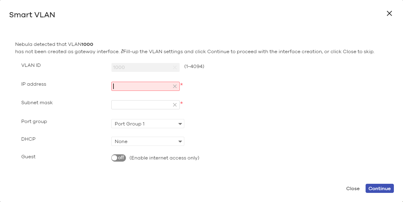 |
Band mode | Select to have the SSID use either 2.4 GHz band only or the 5 GHz band only. If you select Concurrent operation (2.4 GHz and 5 GHz), the SSID uses both frequency bands. You can then turn on Band Select to have the dual-band Nebula Device steer the wireless clients to the 5 GHz band. |
Layer 2 isolation | Select to turn on or off layer-2 isolation. If a device’s MAC addresses is NOT listed, it is blocked from communicating with other devices in an SSID on which layer-2 isolation is enabled. Click Add to enter the MAC address of each device that you want to allow to be accessed by other devices in the SSID on which layer-2 isolation is enabled. |
Intra-BSS traffic blocking | This field is not configurable if you enable Layer 2 isolation. Select on to prevent crossover traffic from within the same SSID. Select off to allow intra-BSS traffic. |
Band select | Select to enable band steering. When enabled, the Nebula Device steers WiFi clients to the 5 GHz band. |
Assisted roaming | Select to turn on or off IEEE 802.11k/v assisted roaming on the Nebula Device. When the connected clients request 802.11k neighbor lists, the Nebula Device will response with a list of neighbor Nebula Devices that can be candidates for roaming. When the 802.11v capable clients are using the 2.4 GHz band, the Nebula Device can send 802.11v messages to steer clients to the 5 GHz band. |
802.11r | Select to turn on or off IEEE 802.11r fast roaming on the Nebula Device. 802.11r fast roaming reduces the delay when the clients switch from one Nebula Device to another, by allowing security keys to be stored on all Nebula Devices in a network. Information from the original association is passed to the new Nebula Device when the client roams. The client does not need to perform the whole 802.1x authentication process. |
U-APSD | Select to turn on or off Automatic Power Save Delivery. This helps increase battery life for battery-powered wireless clients connected to the Nebula Device. |
Captive Portal Customization
Use this screen to configure captive portal settings for SSID profiles. A captive portal intercepts network traffic until the user authenticates his or her connection, usually through a specifically designated login web page.
Click Access Point > Configure > Captive portal customization to access this screen.
Access Point > Configure > Captive portal customization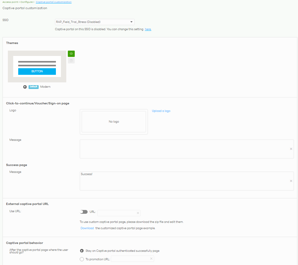
The following table describes the labels in this screen.
Label | Description |
|---|---|
SSID | Select the SSID profile to which the settings you configure here is applied. |
Themes | This section is not configurable when External captive portal URL is set to ON. • Click the Preview icon at the upper right of a theme image to display the portal page in a new frame. • Click the Copy icon to create a new custom theme (login page). • Click the Edit icon of a custom theme to go to a screen where you can view and configure the details of the custom theme pages. See Custom Theme Edit. • Click the Remove icon to delete a custom theme page. Select the theme you want to use on the specified SSID. |
Click-to-continue/Voucher/Sign-on page This section is not configurable when External captive portal URL is set to ON. | |
Logo | This shows the logo image that you uploaded for the customized login page. Click Upload a logo and specify the location and file name of the logo graphic or click Browse to locate it. You can use the following image file formats: GIF, PNG, or JPG. |
Message | Enter a note to display below the title. Use up to 1024 printable ASCII characters. Spaces are allowed. |
Success page | |
Message | Enter a note to display on the page that displays when a user logs in successfully. Use up to 1024 printable ASCII characters. Spaces are allowed. |
External captive portal URL | |
Use URL | Select On to use a custom login page from an external web portal instead of the one built into the NCC. You can configure the look and feel of the web portal page. Specify the login page’s URL; for example, http://IIS server IP Address/login.asp. The Internet Information Server (IIS) is the web server on which the web portal files are installed. Click Download to download a ZIP file containing example captive port files. Edit these files then upload them to a webserver which is accessible from NCC. 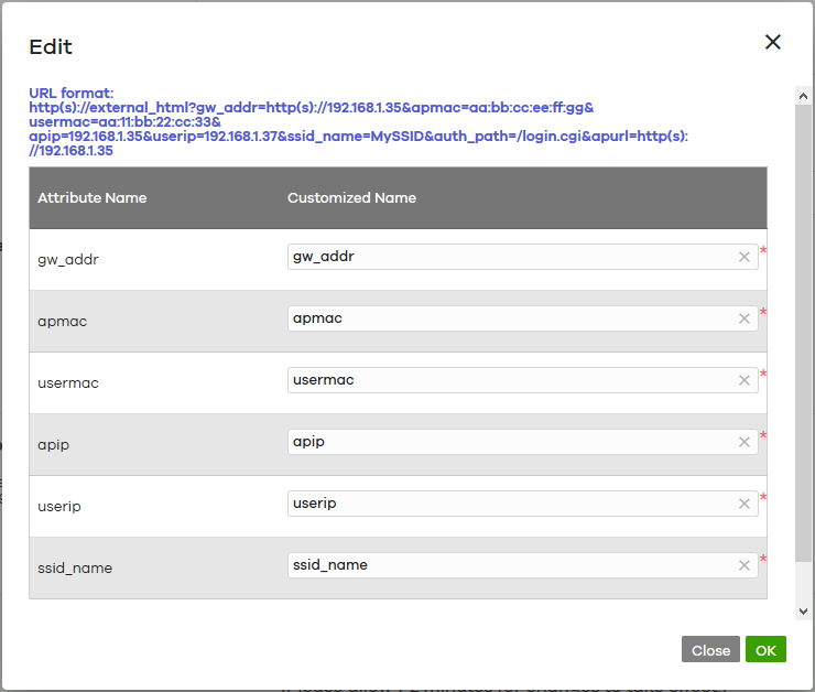 |
Captive portal behavior | |
After the captive portal page where the user should go? | Select To promotion URL and specify the URL of the web site or page to which the user is redirected after a successful login. Otherwise, select Stay on Captive portal authenticated successfully page. |
Custom Theme Edit
Use this screen to check what the custom portal pages look like. You can also view and modify the CSS values of the selected HTML file. Click a custom login page’s Edit button in the Access Point > Configure > Captive portal screen to access this screen.
Access Point > Configure > Captive portal: Edit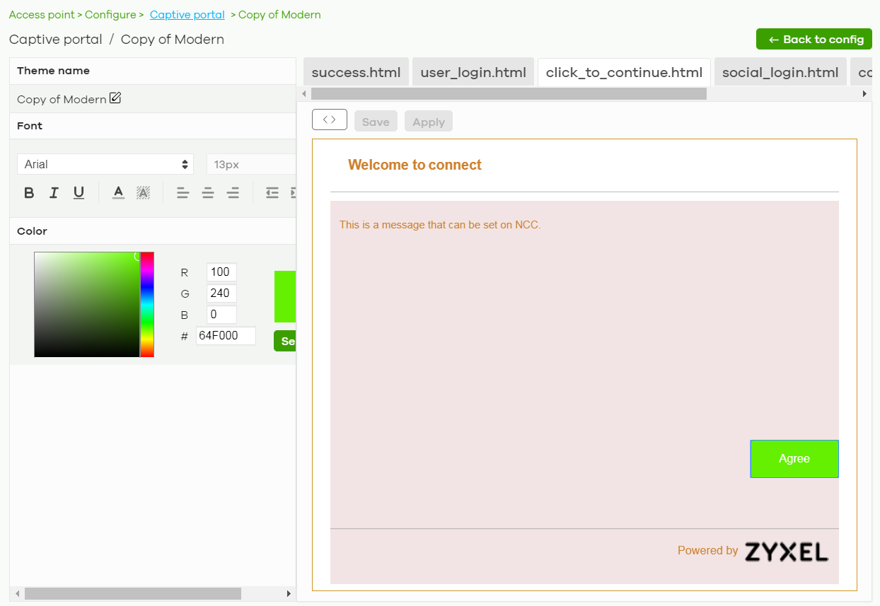
The following table describes the labels in this screen.
Label | Description |
|---|---|
Back to config | Click this button to return to the Captive portal screen. |
Theme name | This shows the name of the theme. Click the edit icon the change it. |
Font | Click the arrow to hide or display the configuration fields. To display this section and customize the font type and/or size, click on an item with text in the preview of the selected custom portal page (HTML file). |
Color | Click the arrow to hide or display the configuration fields. Click an item in the preview of the selected custom portal page (HTML file) to customize its color, such as the color of the button, text, window’s background, links, borders, and so on. Select a color that you want to use and click the Select button. |
HTML/CSS | This shows the HTML file name of the portal page created for the selected custom theme. This also shows the name of the CSS files created for the selected custom theme. Click a HTML file to display the portal page. You can also change colors and modify the CSS values of the selected HTML file. |
Click this button to view and modify the CSS values of the selected HTML file. It is recommended that you do NOT change the script code to ensure proper operation of the portal page. | |
Click this button to preview the portal page (the selected HTML file). | |
Save | Click this button to save your settings for the selected HTML file to the NCC. |
Apply | Click this button to save your settings for the selected HTML file to the NCC and apply them to the APs in the site. |
SSID Availability
Use this screen to configure SSID availability and the schedules which can be applied to the SSIDs. The SSID is enabled or disabled at the specified time. Click Access Point > Configure > SSID availability to access this screen.
Access Point > Configure > SSID availability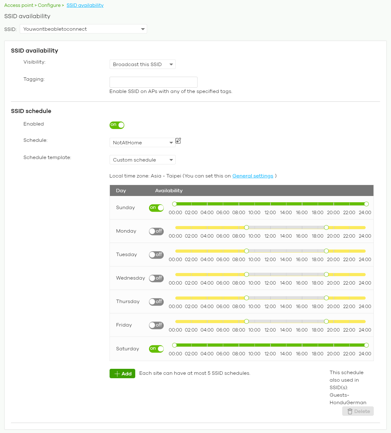
The following table describes the labels in this screen.
Label | Description |
|---|---|
SSID | Select the SSID profile to which the settings you configure here is applied. |
SSID availability | |
Visibility | Select Hide this SSID if you want to hide your SSID from wireless clients. This tells any wireless clients in the vicinity of the Nebula Device using this SSID profile not to display its SSID name as a potential connection. Not all wireless clients respect this flag and display it anyway. Otherwise, select Broadcast this SSID. When an SSID is “hidden” and a wireless client cannot see it, the only way you can connect to the SSID is by manually entering the SSID name in your wireless connection setup screens (these vary by client, client connectivity software, and operating system). |
Tagging | Enter the tags you created for Nebula Devices in the Access Point > Monitor > Access Points screen. The SSID profile will only be applied to Nebula Devices with the specified tag. If you leave this field blank, this SSID profile will be applied to all Nebula Devices in the site. |
SSID schedule | |
Enabled | Click On to enable and configure a schedule. |
Schedule | Select a schedule to control when the SSID is enabled or disabled. You can click the edit icon to change the schedule name. |
Schedule templates | Select a pre-defined schedule template or select Custom schedule and manually configure the day and time at which the SSID is enabled or disabled. |
Day | This shows the day of the week. |
Availability | Click On to enable the SSID at the specified time on this day. Otherwise, select Off to disable the SSID on the day and at the specified time. Specify the hour and minute when the schedule begins and ends each day. |
Add | Click this button to create a new schedule. A window pops up asking you to enter a descriptive name for the schedule for identification purposes. 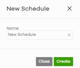 |
Delete | Click this button to remove a schedule which is not used in any SSID profile. |
Radio Settings
Use this screen to configure global radio settings for all Nebula Devices in the site. Click Access Point > Configure > Radio settings to access this screen.
Access Point > Configure > Radio settings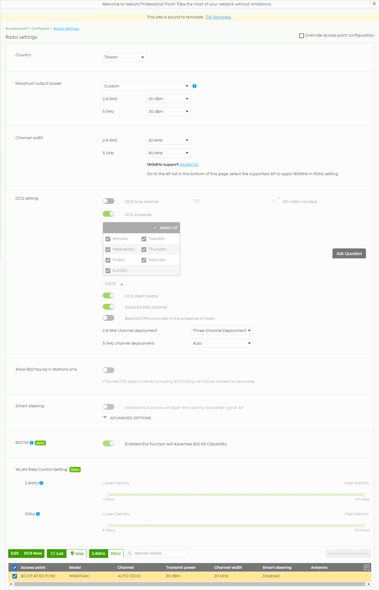
The following table describes the labels in this screen.
Label | Description |
|---|---|
Country | Select the country where the Nebula Device is located or installed. The available channels vary depending on the country you selected. Be sure to select the correct or same country for both radios on an Nebula Device and all connected Nebula Devices in order to prevent roaming failure and interference with other systems. |
Maximum output power | Select High-density deployment for the lowest output power for 10 or more Access Points. Select Moderate-density deployment for moderate output power for 5 to 9 Access Points. Select Low-density deployment for the highest concentration of output power for less than 5 Access Points. Select Custom for setting the maximum target output power of the radio (1 – 30 dBm). |
Channel width | Select the wireless channel bandwidth you want the AP to use. A standard 20 MHz channel offers transfer speeds of up to 144 Mbps (2.4 GHz) or 217 Mbps (5 GHz) whereas a 40 MHz channel uses two standard channels and offers speeds of up to 300 Mbps (2.4 GHz) or 450 Mbps (5 GHz). An IEEE 802.11ac-specific 80 MHz channel offers speeds of up to 1.3 Gbps. 40 MHz (channel bonding or dual channel) bonds two adjacent radio channels to increase throughput. An 80 MHz channel consists of two adjacent 40 MHz channels. The wireless clients must also support 40 MHz or 80 MHz. It is often better to use the 20 MHz setting in a location where the environment hinders the wireless signal. |
DCS setting | |
DCS time interval | Select ON to set the DCS time interval (in minutes) to regulate how often the Nebula Device surveys the other Nebula Devices within its broadcast radius. If the channel on which it is currently broadcasting suddenly comes into use by another Nebula Device, the Nebula Device will then dynamically select the next available clean channel or a channel with lower interference. |
DCS schedule | Select ON to have the Nebula Device automatically find a less-used channel within its broadcast radius at a specific time on selected days of the week. You then need to select each day of the week and specify the time of the day (in 24-hour format) to have the Nebula Device use DCS to automatically scan and find a less-used channel. |
DCS client aware | Select ON to have the Nebula Device wait until all connected clients have disconnected before switching channels. |
Avoid 5G DFS channel | If your Nebula Devices are operating in an area known to have RADAR devices, the Nebula Device will choose non-DFS channels to provide a stable wireless service. |
Blacklist DFS channels in the presence of radar | Select ON to blacklist a channel if RADAR is detected. After being blacklisted, the Nebula Device will not use the channel again until the Nebula Device is rebooted. However, the Nebula Device can still use other DFS channels. |
2.4 GHz channel deployment | Select Three-Channel Deployment to limit channel switching to channels 1, 6, and 11, the three channels that are sufficiently attenuated to have almost no impact on one another. In other words, this allows you to minimize channel interference by limiting channel-hopping to these three “safe” channels. Select Four-Channel Deployment to limit channel switching to four channels. Depending on the country domain, if the only allowable channels are 1 – 11 then the Nebula Device uses channels 1, 4, 7, 11 in this configuration; otherwise, the Nebula Device uses channels 1, 5, 9, 13 in this configuration. Four channel deployment expands your pool of possible channels while keeping the channel interference to a minimum. Select Manual to select the individual channels the Nebula Device switches between. |
5 GHz channel deployment | Select how you want to specify the channels the Nebula Device switches between for 5 GHz operation. Select Auto to have the Nebula Device automatically select the best channel. Select Manual to select the individual channels the Nebula Device switches between. |
Allow 802.11ax/ac/n stations only | Select ON to have the Nebula Device allow only IEEE 802.11n/ac/ax clients to connect, and reject IEEE 802.11a/b/g clients. |
Smart Steering | Select ON to enable smart client steering on the Nebula Device. Client steering helps monitor wireless clients and drop their connections to optimize the bandwidth when the clients are idle or have a low signal. When a wireless client is dropped they have the opportunity to steer to an Nebula Device with a strong signal. Additionally, dual band wireless clients can also steer from one band to another. Select OFF to disable this feature on the Nebula Device. |
ADVANCED OPTIONS | Click this to display a greater or lesser number of configuration fields. |
2.4G/5G Setting | |
Station Signal Threshold | Set a minimum client signal strength. A wireless client is allowed to connect to the Nebula Device only when its signal strength is stronger than the specified threshold. –20 dBm is the strongest signal you can require and –105 dBm is the weakest. |
Disassociate Station Threshold | Set a minimum kick-off signal strength. When a wireless client’s signal strength is lower than the specified threshold, the Nebula Device disconnects the wireless client. –20 dBm is the strongest signal you can require and –105 dBm is the weakest. |
Allow Station Connection after Multiple Retries | Select the check box to allow a wireless client to try to associate with the Nebula Device again after it is disconnected due to weak signal strength. |
Station Retry Count | Set the maximum number of times a wireless client can attempt to re-connect to the Nebula Device. |
802.11d | Click this to enable 802.11d on the AP. 802.11d is a wireless network specification, for use in countries where 802.11 WiFi is restricted. Enabling 802.11d causes the Nebula Device to broadcast the country where it is located, which is determined by the Country setting. |
WLAN Rate Control Setting | |
2.4Ghz/5Ghz | Sets the minimum data rate that 2.4 GHz and 5 GHz WiFi clients can connect to the Nebula Device, in Mbps. Increasing the minimum data rate can reduce network overhead and improve WiFi network performance in high density environments. However, WiFi clients that do not support the minimum data rate will not be able to connect to the Nebula Device. |
Edit | Click this button to modify the channel, output power, channel width and smart steering settings for the selected Nebula Devices. On the Nebula Device that comes with internal antennas and also has an antenna switch, you can adjust coverage depending on the orientation of the antenna for the Nebula Device radios. Select Wall if you mount the Nebula Device to a wall. Select Ceiling if the Nebula Device is mounted on a ceiling. You can switch from Wall to Ceiling if there are still wireless dead zones, and vice versa. If you select Hardware Switch, you use the physical antenna switch to adjust coverage and apply the same antenna orientation settings to both radios. |
DCS Now | Click this button to have the selected Nebula Devices immediately scan for and select a channel that has least interference. |
List | Click this to display a list of all connected Nebula Devices. |
Map | Click this to display the locations of all connected Nebula Devices on the Google map. |
2.4 GHz | Click this to display the connected Nebula Devices using the 2.4 GHz frequency band. |
5 GHz | Click this to display the connected Nebula Devices using the 5 GHz frequency band. |
Hide transmit circles | Click this button to not show the transmission range on the Map. |
Access point | This displays the descriptive name or MAC address of the connected Nebula Device. |
Radio # | This displays the number of the connected Nebula Device’s radio. |
Model | This displays the model name of the connected Nebula Device. |
Radio mode | This displays the type of WiFi radio the Nebula Device is currently using, for example 802.11b/g/n. |
Channel | This displays the channel ID currently being used by the connected Nebula Device’s radio. |
Transmit power | This displays the current transmitting power of the connected Nebula Device’s radio. If the Nebula Device is off-line, this shows the maximum output power you configured for the Nebula Device. |
Channel width | This displays the wireless channel bandwidth the connected Nebula Device’s radio is set to use. |
Smart steering | This displays whether smart client steering is enabled or disabled on the connected Nebula Devices. |
Antenna | This displays the antenna orientation settings for the Nebula Device that comes with internal antennas and also has an antenna switch. |
AP & Port Settings
Use this screen to configure general Nebula Device settings and network traffic load balancing between the Nebula Devices in the site. This screen also allows you to enable or disable a port on the managed Nebula Device and configure the port’s VLAN settings. The port settings apply to all Nebula Devices that are assigned to the site and have one or more than one Ethernet LAN port (except the uplink port).
Click Access Point > Configure > AP & Port Settings to access this screen.
AP > Configure > AP & Port Settings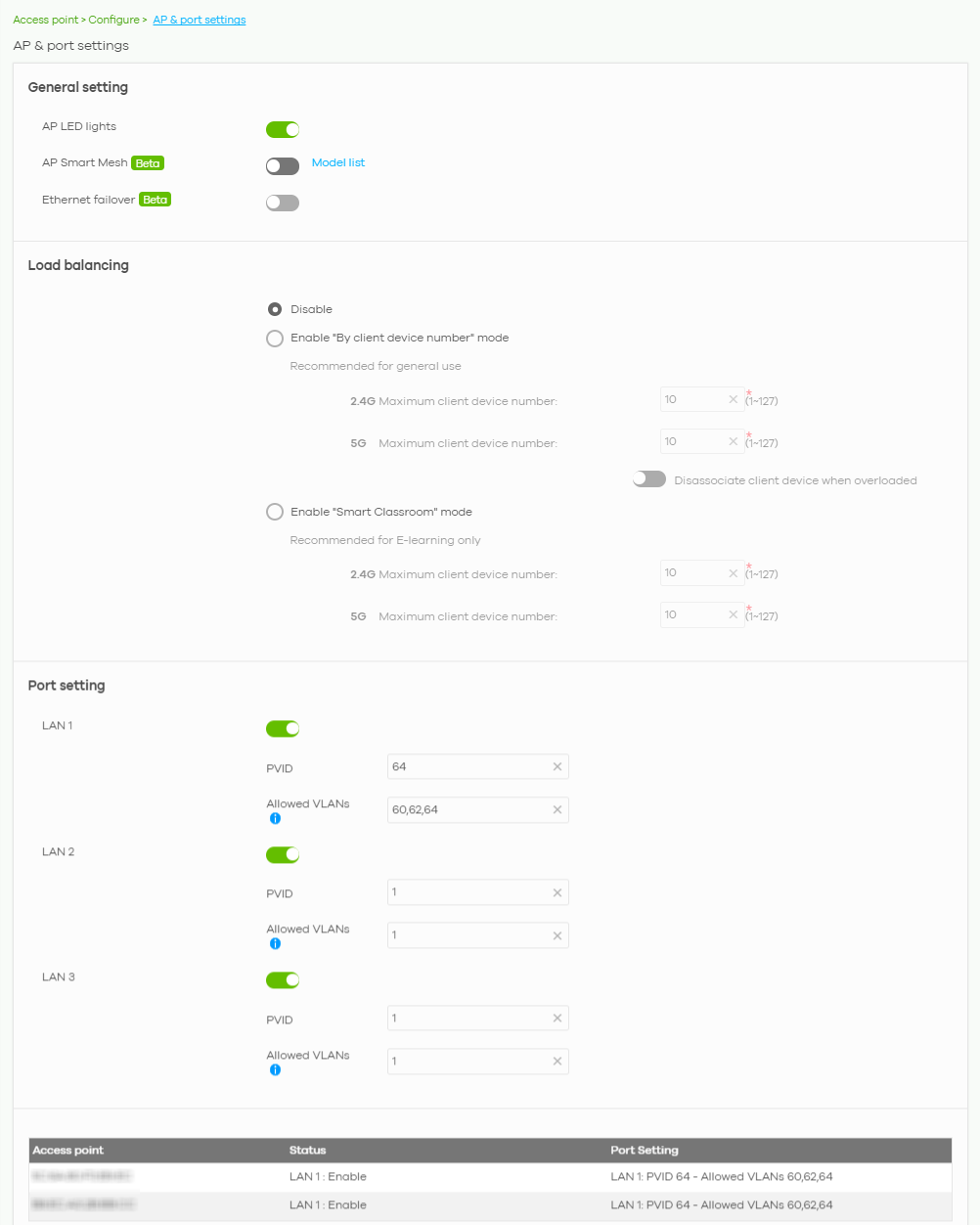
The following table describes the labels in this screen.
Label | Description |
|---|---|
General setting | |
AP LED lights | Click to turn on or off the LEDs on the Nebula Devices. |
AP Smart Mesh | Click to enable or disable the Nebula Smart Mesh feature on all Nebula Devices in the site. Click Model list to see whether your Nebula Device supports Nebula Smart Mesh. |
Ethernet failover | When enabled, a wired Nebula Device in the site automatically changes its role from root Nebula Device to repeater Nebula Device if the Nebula Device is unable to reach the site’s gateway. When disabled, a wired Nebula Device in the site automatically changes its role from root Nebula Device to repeater Nebula Device only if the Nebula Device’s uplink Ethernet cable is unplugged. |
Load balancing | |
Disable | Select this option to disable load balancing on the Nebula Device. |
Enable "By client device number" mode | Select this option to balance network traffic based on the number of specified client devices connected to the Nebula Device. |
Maximum client device number | Enter the threshold number of client devices at which the Nebula Device begins load balancing its connections. |
Disassociate client device when overloaded | Select ON to disassociate wireless clients connected to the Nebula Device when it becomes overloaded. Select OFF to disable this option, then the Nebula Device simply delays the connection until it can afford the bandwidth it requires, or it transfers the connection to another Nebula Device within its broadcast radius. The disassociation priority is determined automatically by the Nebula Device and is as follows: • Idle Time – Devices that have been idle the longest will be disassociated first. If none of the connected devices are idle, then the priority shifts to Signal Strength. • Signal Strength – Devices with the weakest signal strength will be disassociated first. |
Enable "Smart Classroom" mode | Select this option to balance network traffic based on the number of specified client devices connected to the Nebula Device. The Nebula Device ignores association request and authentication request packets from any new client device when the maximum number of client devices is reached. The Disassociate client device when overloaded function is enabled by default and the disassociation priority is always Signal Strength when you select this option. |
Maximum client device number | Enter the threshold number of client devices at which the Nebula Device begins load balancing its connections. |
Port setting | |
LAN x | This is the name of the physical Ethernet port on the Nebula Device. This section lets you configure global port VLAN settings for all Nebula Devices in the site. To modify port settings for a specific Nebula Device, use its Edit button in the table below. |
ON/OFF | Select ON to turn on the LAN port of the Nebula Device. Select OFF to disable the port. |
PVID | Enter the port’s PVID. A PVID (Port VLAN ID) is a tag that adds to incoming untagged frames received on a port so that the frames are forwarded to the VLAN group that the tag defines. |
Allowed VLANs | Enter the VLAN ID numbers to which the port belongs. You can enter individual VLAN ID numbers separated by a comma or a range of VLANs by using a dash, such as 1,3,5–8. |
Access Point | This displays the descriptive name or MAC address of the connected Nebula Device. Only the Nebula Device that has an extra Ethernet LAN port will be listed, such as NAP203 or NAP303. |
Status | This shows whether the Nebula Device’s Ethernet LAN port is enabled or disabled. |
Port Setting | This displays the port’s VLAN settings for the managed Nebula Device. |
Edit Port Settings
Click an entry in the Port setting table of the AP > Configure > AP & Port Settings screen to access this screen.
By default, all Nebula Devices in the site use the global port settings. Use this screen to change the port settings on a per-device basis. You can turn on or off the port, modify its PVID or update the ID number of VLANs to which the port belongs.
AP > Configure > AP & Port Settings: Edit