Configure
Use the Configure menus to configure port setting, IP filtering, RADIUS policies, PoE schedules, and other Nebula Device settings for Nebula Devices of the selected site.
Switch Ports
Use this screen to view port summary and configure Nebula Device settings for the ports. To access this screen, click Site-wide > Configure > Switches > Switch ports or click the Configure ports button in the Site-wide > Devices > Switch: Switch Details screen.
Site-wide > Configure > Switches > Switch ports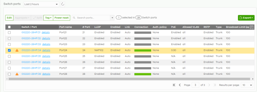
The following table describes the labels in this screen.
Label | Description |
|---|---|
Switch ports | Select to view the detailed information and connection status of the Nebula Device port in the past two hours, day, week or month. |
 | Click this button to reload the data-related frames on this page. |
Edit | Select the ports you want to configure and click this button to configure Nebula Device settings on the ports, such as link aggregation, PoE schedule, LLDP and STP. |
Aggregate | Select more than one port and click this button to group the physical ports into one logical higher-capacity link. |
Split | Select a trunk group and click this button to delete the trunk group. The ports in this group then are not aggregated. A trunk group is one logical link containing multiple ports. |
Tag | Click this button to create a new tag or delete an existing tag. |
Power reset | Click this button to reboot the PD (powered device) connected to the PoE port. Follow the prompt and click Confirm to reboot the PD connected to this port. |
Search | Specify your desired filter criteria to filter the list of Nebula Device ports. You can filter the search by selecting one or more Nebula Devices. Under Ports, you can search for multiple ports separated by a comma, or a range separated by a hyphen. For example: 1,2,4–6. |
Switch ports | This shows the number of ports on the Nebula Device. |
Export | Click this button to save the Nebula Device port list as a CSV or XML file to your computer. |
CRC alert icon | This prompt appears if CRC errors are detected in the port(s). Go to Site-wide > Devices > Switches: Switch Details: Port Details for the details. See Switch Details for more information. |
Switch / Port | This shows the Nebula Device name and port number. If the port is added to a trunk group, this also shows whether it is configured as a static member of the trunk group (Static) or configured to join the trunk group through LACP (LACP). If the port is connected to an uplink gateway, it shows Uplink. If the port is a stacking port, it shows the stacking name, slot ID and port number. Click details to display the port details screen. See Switch Details. |
Port name | This shows the descriptive name of the port. |
Port profiles | This shows the name of the port profile applied on this port. |
#Port | This shows the port number. |
LLDP | This shows whether Link Layer Discovery Protocol (LLDP) is supported on the port. |
Received broadcast packets | This shows the number of good broadcast packets received. |
Received bytes | This shows the number of bytes received on this port. |
Received packets | This shows the number of received frames on this port. |
Sent broadcast packets | This shows the number of good broadcast packets transmitted. |
Sent bytes | This shows the number of bytes transmitted on this port. |
Sent multicast packets | This shows the number of good multicast packets transmitted. |
Received multicast packets | This shows the number of good multicast packets received. |
Sent packets | This shows the number of transmitted frames on this port. |
Total bytes | This shows the total number of bytes transmitted or received on this port. |
Enabled | This shows whether the port is enabled or disabled. |
Link | This shows the speed of the Ethernet connection on this port. Auto (auto-negotiation) allows one port to negotiate with a peer port automatically to obtain the connection speed and duplex mode that both ends support. |
Connection | This shows the connection status of the port. • Gray (#888888): The port is disconnected. • Orange (#FF8900): The port is connected and is transmitting data at 10 or 100 Mbps. • Green (#64BE00): The port is connected and is transmitting data at 1000 Mbps (1 Gbps). • Azure (#00B2FF): The port is connected and is transmitting data at 2.5 Gbps. • Violet (#8800FF): The port is connected and is transmitting data at 5 Gbps. • Blue (#004FEE): The port is connected and is transmitting data at 10000 Mbps (10 Gbps). When the port is in the STP blocking state, failed LACP negotiation state, or failed port authentication state, a blocked icon displays. Move the cursor over a time slot to see the actual date and time when a port is connected or disconnected. |
Auth. policy | This shows the name of authentication policy applied to the port. |
Allowed VLAN | This shows the VLANs from which the traffic comes is allowed to be transmitted or received on the port. |
PoE | This shows whether PoE is enabled on the port. |
RSTP | This shows whether RSTP is enabled on the port. |
Status | If STP/RSTP is enabled, this field displays the STP state of the port. If STP/RSTP is disabled, this field displays FORWARDING if the link is up, otherwise, it displays Disabled. |
Schedule | This shows the name of the PoE schedule applied to the port. |
Type | This shows the port type (Trunk or Access). |
PVID | This shows the port VLAN ID. It is a tag that adds to incoming untagged frames received on the port so that the frames are forwarded to the VLAN group that the tag defines. |
Tag | This shows the user-specified tag that the Nebula Device adds to the outbound traffic on this port. |
Storm Control | This shows whether traffic storm control is enabled or disabled on the port. |
Broadcast Limit (pps) | This shows the maximum number of broadcast packets the Nebula Device accepts per second on this port. |
Multicast Limit (pps) | This shows the maximum number of multicast packets the Nebula Device accepts per second on this port. |
DLF Limit (pps) | This shows the maximum number of Destination Lookup Failure (DLF) packets the Nebula Device accepts per second on this port. |
Loop Guard | This shows whether loop guard is enabled or disabled on the port. |
Network Analytic Alert | An amber alert icon displays if the NCC generates alerts when an error or something abnormal is detected on the port for the IPTV network. Move the cursor over the alert icon to view the alert details. |
IPSG protected | This shows whether IP source guard protection is enabled on this port. |
Received CRC packets | This shows the number of CRC (Cyclic Redundancy Check) errors received on the port. |
Number of IGMP Group | This shows the number of IGMP groups the port has joined. |
Mgmt VLAN control | This shows if management control is enabled on this port. See Site-wide > Configure > Switches > Switch ports: Edit for more information. When the Nebula Device’s Set IP address: Global VLAN configuration is disabled, the Nebula Device’s management VLAN will use its individual VLAN settings rather than the site-wide management VLAN ID. |
Flow control | This shows if flow control is enabled on this port. See Site-wide > Configure > Switches > Switch ports: Edit for more information. |
 | Click this icon to display a greater or lesser number of configuration fields. |
Update ports
Click to select the port you want to configure in the Site-wide > Configure > Switches > Switch ports screen.
Site-wide > Configure > Switches > Switch ports: Edit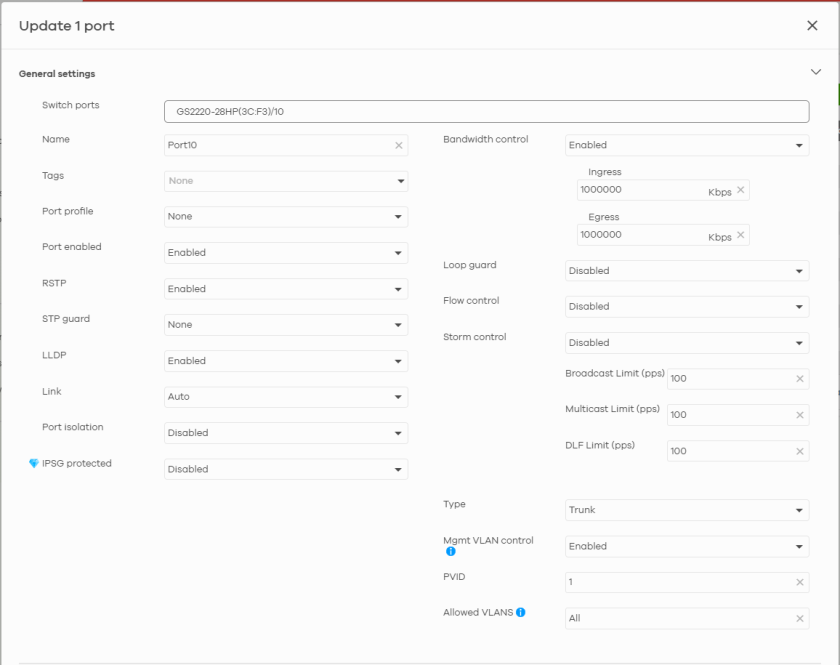
The following table describes the labels in this screen.
Label | Description |
|---|---|
Switch ports | This shows the Nebula Device name and port number for the ports you are configuring in this screen. |
Name | Enter a descriptive name for the ports. |
Tags | Select or create a new tag for outgoing traffic on the ports. |
Port profile | Select the port profile you created in Site-wide > Configure > Switches > Port profiles > Create port profile and make sure to enable this port profile to apply to this port. |
Port enabled | Select to enable or disable the ports. A port must be enabled for data transmission to occur. |
RSTP | Select to enable or disable RSTP (Rapid Spanning Tree Protocol) on the ports. RSTP detects and breaks network loops and provides backup links between switches, bridges or routers. It ensures that only one path exists between any two stations on the network. |
STP guard | This field is available only when RSTP is enabled on the ports. Select Root guard to prevent the Nebula Devices attached to the ports from becoming the root bridge. Select BPDU guard to have the Nebula Device shut down the ports if there is any BPDU received on the ports. Otherwise, select None. |
LLDP | Select to enable or disable LLDP (Link Layer Discovery Protocol) on the ports. LLDP allows the connected network device to advertise its identity and capabilities on the local network. |
Link | Select the speed and the duplex mode of the Ethernet connection on the ports. Choices are 10M/Half Duplex, 10M/Full Duplex, 100M/Half Duplex, 100M/Full Duplex, 1000M/Full Duplex, Auto, 10M/AN, and 100M/AN (Gigabit connections only). |
Extended range | Select to enable or disable extended range. Extended range allows the port to transmit power and data at a distance of 250 meters. |
Media type | You can insert either an SFP+ transceiver or an SFP+ Direct Attach Copper (DAC) cable into the 10 Gigabit interface of the Nebula Device. Select the media type (SFP+ or DAC 10G) of the SFP+ module that is attached to the 10 Gigabit interface. |
FEC | To minimize signal degradation of data at high transmission speeds (for example, 25 Gbps or 100 Gbps), set the same FEC (Forward Error Correction) type between the Nebula Device and the connected device. Select Auto to allow both connected ports to automatically set the FEC type according to the following rules: • For 10G transceivers, the FEC type on the port will automatically be None. • For 25G transceivers, the FEC type on the port will automatically be CL108. • For 100G transceivers, the FEC type on the port will automatically be None if the transceiver type is 100G LR4/ER4; all other types of transceiver will automatically be CL91. Select CL74 when both connected ports support 25 Gbps speed and require low latency in data transmission. Select CL91 when both connected ports support 25 Gbps and 100 Gbps speeds. Select CL108 when both connected ports support 25 Gbps speed but low latency in data transmission is not required. Alternatively, select None when you do not need to set the FEC type. |
Port Isolation | Select to enable or disable port isolation on the ports. The ports with port isolation enabled cannot communicate with each other. They can communicate only with the CPU management port of the same Nebula Device and the Nebula Device’s other ports on which the isolation feature is not enabled. |
IPSG protected | Select to enable or disable IP source guard protection on the port. IP source guard checks incoming IPv4 packets on that port. A packet is allowed when it matches any entry in the IPSG binding table. If a user tries to send IPv4 packets to the Nebula Device that do not match an entry in the IPSG binding table, the Nebula Device will drop these packets. The Nebula Device forwards matching traffic normally. |
Auth. policy | This field is available only when you select Access in the Type field. Select the authentication policy type and name of the pre-configured authentication policy that you want to apply to the ports. See Site-wide > Configure > Switches > Authentication for more information on authentication policy type. See Authentication for more information on configuring authentication policy. Select Open if you do NOT want to enable port authentication on the ports. |
Bandwidth Control | Select to enable or disable bandwidth control on the port. Bandwidth control means defining a maximum allowable bandwidth for incoming and/or outgoing traffic flows on a port. |
Ingress | Specify the maximum bandwidth allowed in kilobits per second (Kbps) for the incoming traffic flow on the ports. |
Egress | Specify the maximum bandwidth allowed in kilobits per second (Kbps) for the out-going traffic flow on the ports. |
Loop guard | Select to enable or disable loop guard on the ports. Loop guard allows you to configure the Nebula Device to shut down a port if it detects that packets sent out on that port to the edge of your network loop back to the Nebula Device. While you can use STP (Spanning Tree Protocol) to prevent loops in the core of your network, STP cannot prevent loops that occur on the edge of your network. |
Flow control | Select to enable or disable flow control on all ports. Enable flow control to allow the Nebula Device’s port to send a pause signal to the connected device, and for the connected device to send a pause signal to the Nebula Device. The Nebula Device will temporarily stop sending signals after receiving a pause signal. |
Storm control | Select to enable or disable broadcast storm control on the ports. Storm control limits the number of broadcast, multicast and destination lookup failure (DLF) packets the Nebula Device receives per second on the ports. When the maximum number of allowable packets is reached per second, the subsequent packets are discarded. |
Broadcast Limit (pps) | Specifies the maximum number of broadcast packets the Nebula Device accepts per second on the ports. |
Multicast Limit (pps) | Specifies the maximum number of multicast packets the Nebula Device accepts per second on the ports. |
DLF Limit (pps) | Specifies the maximum number of DLF packets the Nebula Device accepts per second on the ports. |
Type | Set the type of the port. Select Access to configure the port as an access port which can carry traffic for just one VLAN. Frames received on the port are tagged with the port VLAN ID. Select Trunk to configure the port as a trunk port which can carry traffic for multiple VLANs over a link. A trunk port is always connected to a Nebula Device or router. |
Mgmt VLAN control | Select Enabled to configure the port as a management port. This allows the administrator to set the Nebula Device ports through which the device management VLAN traffic is allowed. The default value depends on your setting for the previous Type field. The default value is Enabled when the Type is Trunk. The default value is Disabled when the Type is Access. |
VLAN type | This field is available only when you select Access in the Type field. None: This port is a regular access port and follows the device’s access port rules. Vendor ID based VLAN: Apply the Vendor ID based VLAN settings from Switch > Configure > Switch settings to this port. Voice VLAN: Apply the Voice VLAN settings from Site-wide > Configure > Switches > Switch settings to this port. |
PVID | A PVID (Port VLAN ID or native VLAN) is a tag that adds to incoming untagged frames received on a port so that the frames are forwarded to the VLAN group that the tag defines. Enter a number between 1and 4094 as the port VLAN ID. |
Allowed VLANs | This field is available only when you select Trunk in the Type field. Specify the VLANs from which the traffic comes. You can then transmit or receive traffic on the ports. See Set Up Dynamic VLAN With RADIUS (for Nebula Switches only) for the steps in setting up dynamic VLAN with RADIUS. See Monitor Dynamic VLAN Using Event Logs (for Nebula Switches only) for more information on monitoring dynamic VLANs using event logs. |
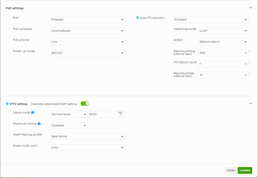
PoE Settings | |
PoE | Select Enabled to provide power to a PD connected to the ports. |
PoE schedule | This field is available only when you enable PoE. Select a pre-defined schedule (created using the Site-wide > Configure > Switches > PoE schedules screen) to control when the Nebula Device enables PoE to provide power on the ports. If you enable PoE and select Unschedule, PoE is always enabled on the ports. Click Edit to go to Site-wide > Configure > Switches > PoE schedules screen to create a new PoE schedule. |
PoE priority | When the total power requested by the PDs exceeds the total PoE power budget on the Nebula Device, you can set the PD priority to allow the Nebula Device to provide power to ports with higher priority. Select Low to set the Nebula Device to assign the remaining power to the port after all critical and medium priority ports are served. Select Medium to set the Nebula Device to assign the remaining power to the port after all critical priority ports are served. Select Critical to give the highest PD priority on the port. |
Power up mode | Set how the Nebula Device provides power to a connected PD at power-up. 802.3at – the Nebula Device supports the IEEE 802.3at High Power over Ethernet standard and can supply power of up to 30W per Ethernet port. IEEE 802.3at is also known as PoE+ or PoE Plus. An IEEE 802.3at compatible device is referred to as Type 2. Power Class 4 (High Power) can only be used by Type 2 devices. If the connected PD requires a Class 4 current when it is turned on, it will be powered up in this mode. 802.3af – the Nebula Device follows the IEEE 802.3af Power over Ethernet standard to supply power to the connected PDs during power-up. Legacy – the Nebula Device can provide power to the connected PDs that require high inrush currents at power-up. Inrush current is the maximum, instantaneous input current drawn by the PD when first turned on. Pre-802.3at – the Nebula Device initially offers power on the port according to the IEEE 802.3af standard, and then switches to support the IEEE 802.3at standard within 75 milliseconds after a PD is connected to the port. Select this option if the Nebula Device is performing 2-event Layer-1 classification (PoE+ hardware classification) or the connected PD is NOT performing Layer 2 power classification using Link Layer Discovery Protocol (LLDP). Force 802.3at – the Nebula Device provides PD Wide Range Detection (WRD) with power of up to 33 W on the port without performing PoE classification. Select this if the connected PD does not comply with any PoE standard. 802.3bt – the Nebula Device follows the IEEE 802.3bt standard to supply power of up to 60 W per Ethernet port to the connected PDs at power-up. Pre-802.3bt – the Nebula Device offers power on the port according to the IEEE 802.3bt standard. Select this if the connected PD was manufactured before the IEEE 802.3bt standard was implemented on September 2018, but requires power between 33 W and 60 W. IEEE 802.3bt is also known as PoE++ or PoE Plus Plus. |
Auto PD recovery | Select to enable or disable automatic PD recovery on the port. Automatic PD recovery allows the Nebula Device to restart a Powered Device (PD) connected to the port by turning the device on and off again. |
Detecting mode | Select LLDP to have the Nebula Device passively monitor current status of the connected Powered Device (PD) by reading LLDP packets from the PD on the port. Select Ping to have the Nebula Device ping the IP address of the connected Powered Device (PD) through the designated port to test whether the PD is reachable or not. |
Action | Set the action to take when the connected Powered Device (PD) has stopped responding. Select Reboot-Alarm to have the Nebula Device send an SNMP trap and generate a log message, and then turn off the power of the connected PD and turn it back on again to restart the PD. Select Alarm to have the Nebula Device send an SNMP trap and generate a log message. |
Neighbor IP | Set the IPv4 address of the Powered Device (PD) connected to this port. |
Polling interval (sec) | Specify the number of seconds the Nebula Device waits for a response before sending another ping request. For example, the Nebula Device will try to detect the PD status by performing ping requests every 20 seconds. |
Polling count | Specify how many times the Nebula Device resends a ping request before considering the PD unreachable. |
Resume polling interval (sec) | Specify the number of seconds the Nebula Device waits before monitoring the PD status again after it restarts the PD on the port. |
PD reboot count | Specify how many times the Nebula Device attempts to restart the PD on the port. The PD Reboot Count resets if any of the following conditions are true: • The Nebula Device successfully pings the PD. • You modify any Auto PD Recovery settings and apply them. • The Nebula Device restarts. |
Resume power interval (sec) | Specify the number of seconds the Nebula Device waits before supplying power to the connected PD again after it restarts the PD on the port. |
IPTV Setting | |
Override advanced IGMP setting | Select ON to overwrite the port’s advanced IGMP settings (configured in the Site-wide > Configure > Switches > Advanced IGMP screen) with the settings you configure in the fields below. Otherwise, select OFF. |
Leave mode | Select Immediate Leave to remove this port from the multicast tree immediately when an IGMP leave message is received on this port. Select this option if there is only one host connected to this port. Select Normal Leave or Fast Leave and enter an IGMP normal/fast leave timeout value to have the Nebula Device wait for an IGMP report before the leave timeout when an IGMP leave message is received on this port. You need to specify how many milliseconds the Nebula Device waits for an IGMP report before removing an IGMP snooping membership entry when an IGMP leave message is received on this port from a host. In Normal Leave mode, when the Nebula Device receives an IGMP leave message from a host on a port, it forwards the message to the multicast router. The multicast router then sends out an IGMP Group-Specific Query (GSQ) message to determine whether other hosts connected to the port should remain in the specific multicast group. The Nebula Device forwards the query message to all hosts connected to the port and waits for IGMP reports from hosts to update the forwarding table. In Fast Leave mode, right after receiving an IGMP leave message from a host on a port, the Nebula Device itself sends out an IGMP Group-Specific Query (GSQ) message to determine whether other hosts connected to the port should remain in the specific multicast group. This helps speed up the leave process. |
Maximum Group | Select Enable and enter the maximum number of multicast groups this port is allowed to join. Once a port is registered in the specified number of multicast groups, any new IGMP join report received on this port will replace the earliest group entry in the multicast forwarding table. Otherwise, select Disable to turn off multicast group limits. |
IGMP filtering profile | An IGMP filtering profile specifies a range of multicast groups that clients connected to the Nebula Device are able to join. Select the name of the IGMP filtering profile to use for this port. Otherwise, select No Select to remove restrictions and allow the port to join any multicast group. |
Fixed router port | Select Auto to have the Nebula Device use the port as an IGMP query port if the port receives IGMP query packets. The Nebula Device forwards IGMP join or leave packets to an IGMP query port. Select Fixed to have the Nebula Device always use the port as an IGMP query port. This helps prevent IGMP network topology changes when query packet losses occur in the network. |
Close | Click this button to exit this screen without saving. |
Update | Click this button to save your changes and close the screen. |
Port Profiles
Use this screen to create profiles that can be applied to each port on the Nebula Device. A port profile can contain features such as RSTP (Rapid Spanning Tree Protocol), STP guard, port isolation, loop guard, storm control, and PoE (Power over Ethernet). To access this screen, click Site-wide > Configure > Switches > Port profiles.
Site-wide > Configure > Switches > Port profiles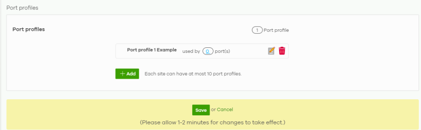
The following table describes the labels in this screen.
Label | Description |
|---|---|
Port profile | This shows the number of port profiles configured on this site. |
used by port(s) | This shows the port profile name and the number of ports that are using this port profile. Click the number to go to the Site-wide > Configure > Switches > Switch ports screen. |
edit | Click this icon to go to Site-wide > Configure > Switches > Port profiles > Update port profile to edit an existing port profile. |
delete | Click this icon to remove the port profile. |
+ Add | Click this button to create a new port profile for Nebula Switches on the site. |
Save | Click Save to save your changes and create the port profile. |
Cancel | Click Cancel to exit this screen without saving. |
Port Profile Configuration
Click the Add button or click the Edit button in the Port profile screen to open the Site-wide > Configure > Switches > Port profiles > Create/Edit port profile screen.
Site-wide > Configure > Switches > Port profiles > Create/Edit port profile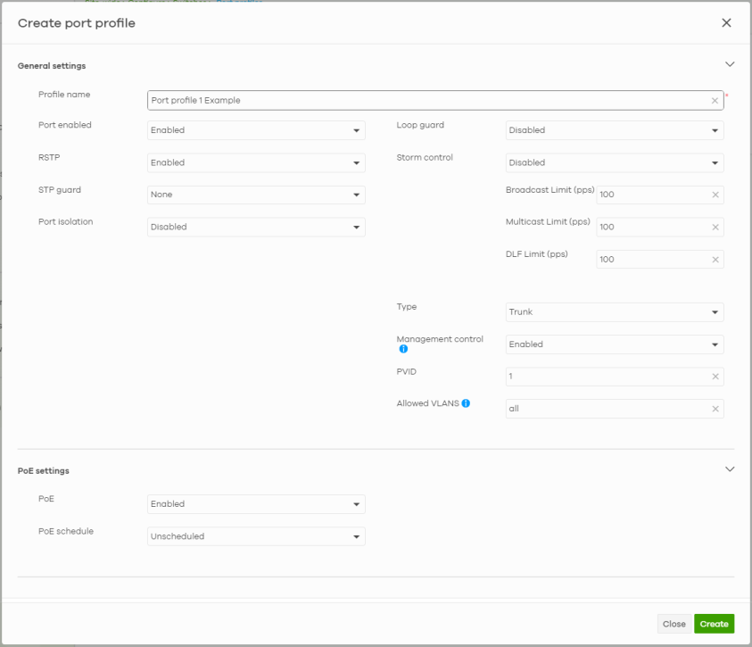
The following table describes the labels in this screen.
Label | Description |
|---|---|
General settings | |
Profile name | Enter a name for this profile for identification purposes. Use up to 127 characters (0 – 9 a – z). The casing does not matter. |
Port enabled | Select to enable or disable the port. A port must be enabled for data transmission to occur. |
RSTP | Select to enable RSTP (Rapid Spanning Tree Protocol) on this profile. RSTP detects and breaks network loops and provides backup links between switches, bridges, or routers. It ensures that only one path exists between any two stations on the network. |
STP guard | This field is available only when RSTP is enabled on this profile. Select Root guard to prevent the Nebula Devices attached to the ports from becoming the root bridge. Select BPDU guard to have the Nebula Device shut down the ports if there is any BPDU received on the ports. Otherwise, select None. |
Port isolation | Select to enable port isolation on the ports. The ports with port isolation enabled cannot communicate with each other. They can communicate only with the CPU management port of the same Nebula Device and the ports on which the isolation feature is disabled. |
Loop guard | Select to enable loop guard on the ports. Loop guard allows you to configure the Nebula Device to shut down a port if it detects that packets sent out on that port to the edge of your network loop back to the Nebula Device. While you can use STP (Spanning Tree Protocol) to prevent loops in the core of your network, STP cannot prevent loops that occur on the edge of your network. |
Storm control | Select to enable broadcast storm control on the ports. Storm control limits the number of broadcast, multicast, and destination lookup failure (DLF) packets the Nebula Device receives per second on the ports. When the maximum number of allowable packets per second is reached, the subsequent packets are discarded. |
Broadcast Limit (pps) | Specify the maximum number of broadcast packets per second the Nebula Device accepts on the ports. |
Multicast Limit (pps) | Specify the maximum number of multicast packets per second the Nebula Device accepts on the ports. |
DLF Limit (pps) | Specify the maximum number of DLF packets per second the Nebula Device accepts on the ports. |
Type | Set the type of the port. Select Access to configure the port as an access port that can carry traffic for just one VLAN. Frames received on the port are tagged with the port VLAN ID. Select Trunk to configure the port as a trunk port to carry traffic for multiple VLANs over a link. A trunk port always connects to a Nebula Device or router. |
Management control | Select Enabled to configure the port as a management port. The default is Enabled. This allows the administrator to set the Nebula Device ports to allow the device to manage VLAN traffic. |
PVID | A PVID (Port VLAN ID or native VLAN) is a tag that adds to incoming untagged frames received on a port so that the frames are forwarded to the VLAN group that the tag defines. Enter a number between 1 and 4094 as the port VLAN ID. |
Allowed VLANs | This field is available only when you select Trunk in the Type field. Specify the VLANs from which the traffic comes. You can then transmit or receive traffic on the ports. See Set Up Dynamic VLAN With RADIUS (for Nebula Switches only) for steps in setting up dynamic VLAN with RADIUS. See Monitor Dynamic VLAN Using Event Logs (for Nebula Switches only) for more information on monitoring dynamic VLANs using event logs. |
PoE settings | |
PoE | Select Enabled to provide power to a PD connected to the ports. |
PoE schedule | This field is available only when you enable PoE. Select a pre-defined schedule (created using the Site-wide > Configure > Switches > PoE schedules screen) to control when the Nebula Device enables PoE to provide power on the ports. If you enable PoE and select Unscheduled, then PoE is always enabled on the ports. Click Edit to go to Site-wide > Configure > Switches > PoE schedules screen to create a new PoE schedule. |
Close | Click this button to exit this screen without saving. |
Create | Click this button to save your changes and close the screen. |
Cloud Stacking Mode
In Cloud Stacking mode, you can stack Nebula Devices using the NCC. You can set the Nebula Device to Cloud Stacking mode and configure the stacking settings on the NCC.
In NCC, a Nebula Device in the stacking system is referred to as a slot. For example, slot 4 refers to the fourth Nebula Device in the stacking system.
From Cloud Mode to Cloud Stacking Mode
Follow the steps below to stack Nebula Devices in Cloud mode:
1 Add the Nebula Devices to your site. See Add a Nebula Device for more information.
2 Use the Create new stacking wizard to add the Nebula Device to a stacking system on the NCC. See Stacking management for more information. The Nebula Device will then go into Cloud Stacking mode.
From Cloud Stacking Mode to Cloud Mode
Follow the steps below to change from Cloud Stacking mode to Cloud mode, that is remove stacking in Cloud Stacking mode:
1 Go to Site-wide > Configure > Switches > Stacking management to remove the Nebula Device from the stack system on the NCC. See Stacking management for more information.
2 Reset the Nebula Device to its factory defaults. The Nebula Device will go to Standalone mode after you reset the Nebula Device, and you will lose all configurations done in NCC.
3 Make sure the Nebula Device can access the NCC and is registered on the NCC. The Nebula Device will then go into Cloud mode.
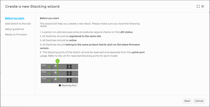
Important Notes
• Someone must be onsite to connect the stacking ports for each Nebula Device and then check the LED status. See the User’s Guide for the stacking ports and LED status for each model. Follow the instructions on the wizard to connect the stacking ports on your Nebula Devices.
• The Nebula Device can only connect to other Nebula Devices of the same model and firmware version.
• NCC allows up to four Nebula Devices in a stack.
• NCC allows up to ten stacks per site.
• Each Nebula Device should have a valid Nebula Professional license.
• Each Nebula Device must belong to the same site in NCC.
• If the NCC detects any connection abnormality in your stack system, the NCC will pause the configuration process until all Nebula Devices in your stacking system are online and connected properly. You can check the stacking system status on the NCC. See Stacking management for more information.
• You cannot switch from 2-Port Mode stacking to 4-Port Mode directly. You need to remove the stacking and re-create the stacking system. See From Cloud Stacking Mode to Cloud Mode for more information on removing stacking. See Create a New Stacking System Wizard for more information on creating the stacking system.
Stacking Nebula Devices
Stacking is directly connecting Nebula Devices to form a larger system that behaves as a single Nebula Device or a virtual chassis with increased port density.
Switch Stacking Concept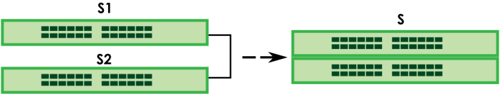
You can manage each Nebula Device in the stack from a master Nebula Device using the NCC.
Each Nebula Device supports up to two stacking channels.
The Nebula Device ports of a stacking channel can only connect to the Nebula Device ports of one stacking channel on the neighboring Nebula Device. A stacking channel cannot simultaneously connect to two different stacking channels on the neighboring Nebula Device. For example, ports 25 and 26 (channel 1) on Nebula Device A can connect to ports 25 and 26 (channel 1) or ports 27 and 28 (channel 2) on Nebula Device B. You cannot connect port 26 (channel 1) on Nebula Device A to port 28 (channel 2) on Nebula Device B while connecting port 25 (channel 1) on Nebula Device A to port 25 (channel 1) on Nebula Device B at the same time.
Stacking Channel and Port Examples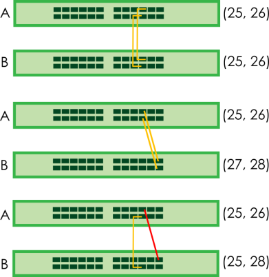
4-Port and 2-Port Stacking Modes (XGS2220 Series)
In 4-port mode, all four 10G stacking ports are used for stacking. Use this mode if you want to stack Nebula Devices with automatic link aggregation giving a stacking connection of 20 Gbps. The default algorithm type is src-dst-mac, and is not configurable.
In 2-port mode, just the last two 10G stacking ports of the Nebula Device are used for stacking. Use this mode if you want to use the first two fiber ports for high-speed connections such as a fiber uplink connection and a connection to a 10G NAS. You may stack Nebula Devices without automatic link aggregation giving a stacking connection of 10 Gbps.
You must make the stacking connections as shown in the following tables.
staCking channel | stacking port | |
|---|---|---|
XGS2220-30 / XGS2220-30HP / XGS2220-30F | 1 | 29 |
2 | 30 | |
XGS2220-54 / XGS2220-54HP / XGS2220-54FP | 1 | 53 |
2 | 54 |
staCking channel | stacking ports | |
|---|---|---|
XGS2220-30 / XGS2220-30HP / XGS2220-30F | 1 | 27, 28 |
2 | 29, 30 | |
XGS2220-54 / XGS2220-54HP / XGS2220-54FP | 1 | 51, 52 |
2 | 53, 54 |
Stacking Channel | Stacking Ports | |
|---|---|---|
XS3800-28 | 1 | 25, 26 |
2 | 27, 28 |
XGS2220 Series with firmware version ZyNOS 4.80 (patch 4) and later supports Cloud Stacking mode. See Cloud Stacking Mode for more information on Cloud Stacking mode.
Chain Topology and Ring Topology
You can build a Nebula Device stack using a ring or chain topology.
In a chain (C) topology, each Nebula Device connects to the next Nebula Device with the last Nebula Device connected to the Nebula Device before it. If Nebula Device 3 fails, then only Nebula Devices 1 and 2 will still function.
In a ring (R) topology, each Nebula Device connects to the next Nebula Device with the last Nebula Device connected to the first. If Nebula Device 3 fails, then Nebula Devices 1, 2 and 4 will function as a chain topology.
Stacking Topology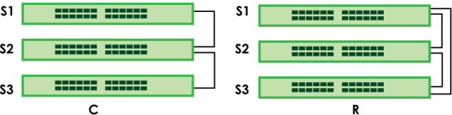
Stacking will automatically choose a master Nebula Device. The Nebula Device with the longest up-time is selected. Uptime is measured in increments of 10 minutes. The Nebula Device with the higher number of increments is selected. If they have the same uptime, then the Nebula Device with the lowest MAC address will be the master.
This is the master election priority in a stack system:
1 Longest uptime
2 Lowest MAC address.
– a stacking port cable is disconnected
– a Nebula Device in the stack reboots
– you add a Nebula Device to the stack or
– a Nebula Device in the stack shuts down.
Stacking management
Use this screen to create a stack, configure the stack settings, and view the stack status of Nebula Devices on the NCC.
Click Site-wide > Configure > Switches > Stacking management to access this screen.
Site-wide > Configure > Switches > Stacking management 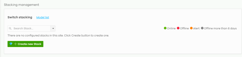
The following table describes the labels in this screen.
Label | Description |
|---|---|
Stack status/Name/Members | Use this field to display the stacking system configured in NCC using criteria such as Stack status/Name/Members. |
Status | This shows the status of the stacking system. • Green – all the Nebula Devices in the stacking system are online and the stack is configured correctly. • Green with lock icon – NCC has locked the stack system because it lacks provisioning. NCC needs to apply the site-wide port settings to all Nebula Devices in the stacking system (provisioning). To unlock, click the Provision button. See Create a New Stacking System Wizard for more information. • Orange with lock icon – NCC has locked the stacking system because of one of the following reasons: One or more Nebula Devices are offline. Make sure all the stacking ports of the Nebula Devices are connected, the power is on, and one Nebula Device is connected to the Internet. You removed a Nebula Device from the stacking system in NCC but did not disconnect the onsite stacking cable. Disconnect the stacking cable. NCC has detected that the onsite Nebula Device’s cable connection does not match the Slot ID configuration in NCC. • Red – the stacking system is offline. Make sure a Nebula Device has Internet connection. • Gray – the stacking system is offline for more than six days. |
Name | This shows the NCC-assigned name of the stacking system. To change, click the Name to go to the Slot management screen. Click the Name on any Nebula Device to go to the Site-wide > Devices > Switches detail screen. See Switches for more information. |
Model | This shows the model type of the Nebula Device in the stacking system. |
Configuration status | This shows Up to date when NCC has finished applying the site-wide settings to the stacking Nebula Device. Otherwise, it shows Not up to date. |
Current version | This shows the ZyNOS firmware that is currently running on the Nebula Devices in the stacking system. |
Slot | This shows the Nebula Device’s name in the stacking system. |
Stacking mode | This shows the number of stacking ports. 2-port means the last 2 SFP+ slots are dedicated for Nebula Device stacking. 4-port means the last 4 SFP+ slots are dedicated for Nebula Device stacking. |
Media type | This shows the media type (SFP+ or DAC) of the SFP+ module that is attached to the 10 Gigabit interface. |
Delete | Click this when you want to remove the stacking system on the NCC. The Nebula Devices will appear as individual devices in NCC. Reset the Nebula Devices to factory-default settings so that the Nebula Devices will not appear offline in NCC. Follow the steps in From Cloud Stacking Mode to Cloud Mode to change from Cloud Stacking mode to Cloud mode. |
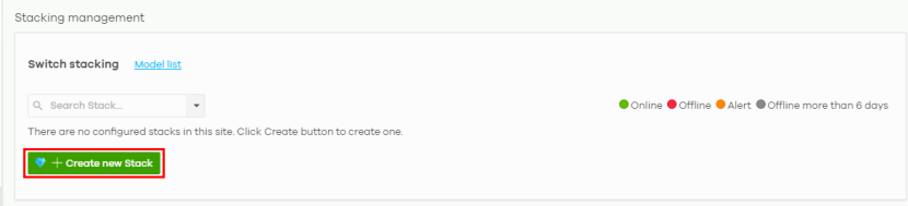
Create new Stack | Click this button to run the Create a new Stacking wizard. See the next section for more information. |
Create a New Stacking System Wizard
The wizard helps you create a stacking system quickly.
Step1: Run the Wizard
Go to Site-wide > Configure > Switches > Stacking management and click Create new Stack.
Step2: Before you start
Make sure to do the steps listed on the screen. Then click Next.
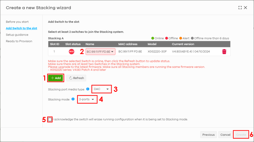
Step3: Add slot
1 Click +Add (1) and then select the first Nebula Device in the Name field (2) to add to the stacking system. Click +Add (1) and then select the second Nebula Device in the Name field (2) to add to the stacking system.
2 Select the media type (SFP+ or DAC) (3) of the SFP+ module to attach to the stacking port.
3 Select the number of stacking ports (2-ports or 4-ports) (4).
Slot ID Sequence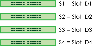
4 Click the I acknowledge the Switch will erase running configuration when it is set to Stacking mode checkbox (5). This means that you will lose all configurations made in NCC for each Nebula Device. You cannot back up the configurations in NCC first.
5 Then click Create (6). The Nebula Devices will automatically reboot to Cloud Stacking mode. NCC will assign the Slot ID to each Nebula Device.
• There are at least two online Nebula Devices in the stacking system
• The ‘erase running configuration’ confirmation box is selected.
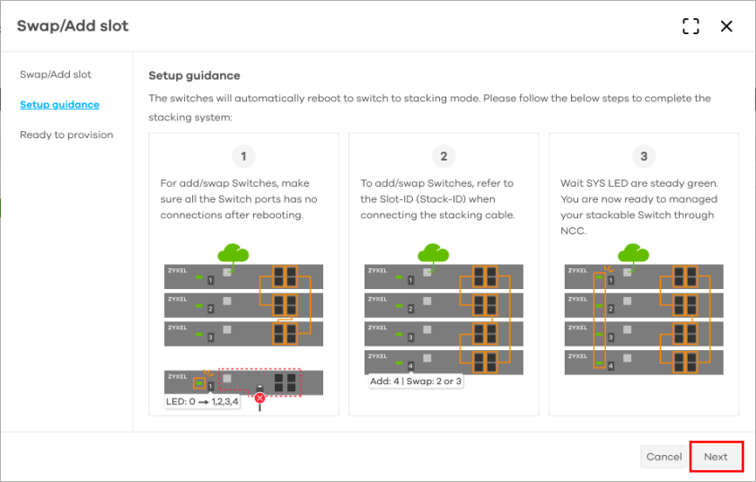
Step4: Setup guidance (onsite hardware connections)
1 Perform the hardware connections onsite. See Hardware Connections (for Stacking) for the steps.
2 Then click Next.
Setup Guidance (2-Port Mode) 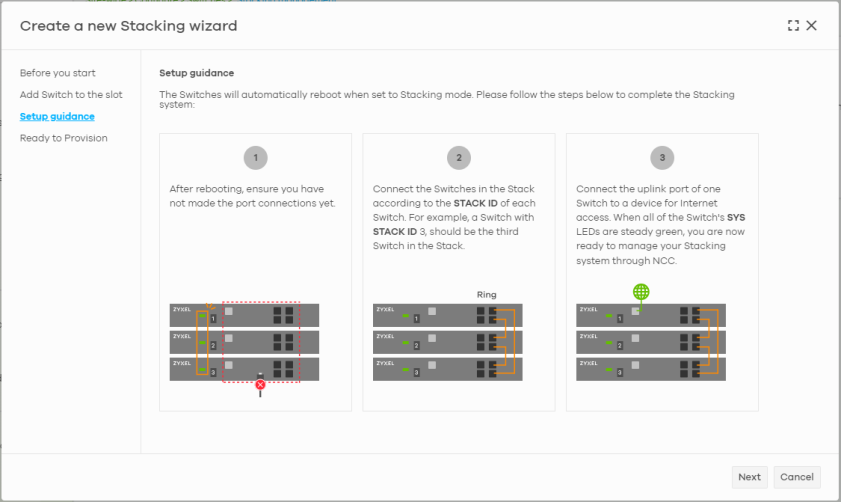
Setup Guidance (4-Port Mode) 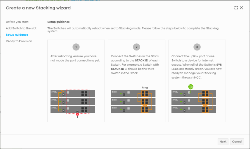
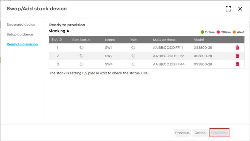
Step5: Ready to Provision
NCC must apply the site-wide port settings to all Nebula Devices in the stack. The Slot Status of the stacking Nebula Device appear green in the following screen when:
• All the Nebula Devices in the stacking system are online
• The Nebula Device connection order matches the Slot ID configuration in NCC.
Click Provision to apply the site-wide port settings and exit the wizard.
Ready to Provision 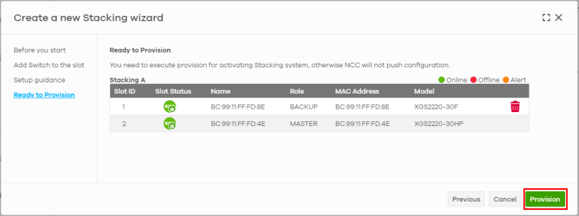
The following screen appears when:
• One or more Nebula Devices in the stacking system are offline
• You remove a Nebula Device from the stacking system in NCC, but did not disconnect the onsite stacking port cable
• The Nebula Device’s onsite cable connection does not match the Slot ID configuration in NCC.
After fixing the problem, click Refresh to have NCC update the stacking status. Click Provision when each stacking Nebula Device’s Slot Status shows green with lock icon.
Not Ready to Provision 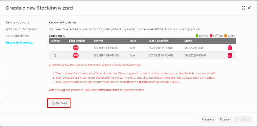
Hardware Connections (for Stacking)
Do the following steps onsite:
1 Remove all Ethernet cable connections from all ports on all the Nebula Devices that are going to be in the stacking system.
2 Check the STACK ID LED on each Nebula Device to find the Slot ID. Position the Nebula Devices accordingly.
Nebula Device STACK ID LED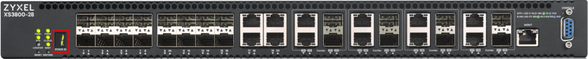
3 Connect the stacking cables to the stacking ports. See the example figure below.
• Ports 25 and 26 (channel 1) on Slot ID 1 (S1) connects to ports 27 and 28 (channel 2) on Slot ID 2 (S2).
• Ports 25 and 26 (channel 1) on Slot ID 2 (S2) connects to ports 27 and 28 (channel 2) on Slot ID 3 (S3).
• Ports 25 and 26 (channel 1) on Slot ID 3 (S3) connects to ports 27 and 28 (channel 2) on Slot ID 4 (S4).
• Ports 25 and 26 (channel 1) on Slot ID 4 (S4) connects to ports 27 and 28 (channel 2) on Slot ID 1 (S1).
Onsite Stacking Cable Connection: Ring Topology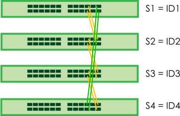
4 Connect one Nebula Device’s uplink Ethernet port only to the Internet for the stacking system.
5 Wait until all the Nebula Device’s SYS LED are steady green. You are now ready to manage your stacking system through NCC.
Slot Management
Use this screen to add, remove, or swap Nebula Devices in a stacking system. Click Site-wide > Configure > Switches > Stacking management, then click the name of the stacking system to access this screen.
Site-wide > Configure > Switches > Stacking management: Slot management 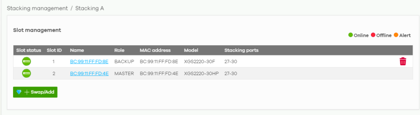
Remove a non-Master Nebula Device
To remove a Nebula Device except the master in a stacking system, do the following:
1 Select the Nebula Device you want to remove. Then click the delete icon on the right.
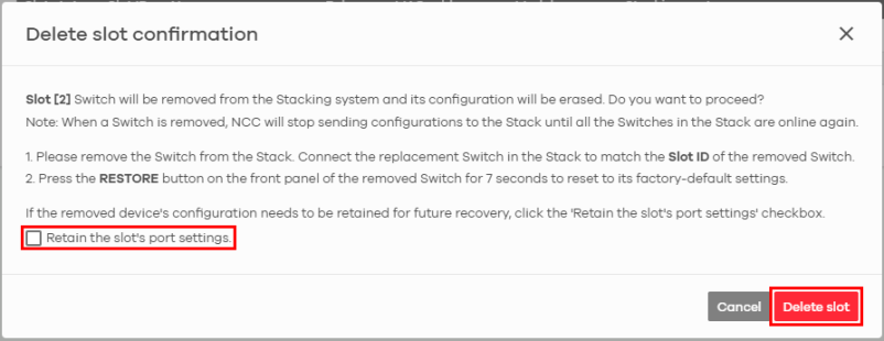
2 The following pop-up window appears. Select Retain the slot’s port setting if you want to apply the setting to the new Nebula Device. Then, click Delete slot.

3 Disconnect the stacking cable on the Nebula Device onsite.
4 Press the RESTORE button on the front panel of the Nebula Device for more than 7 seconds to reset to the factory-default settings.
Remove a Master Nebula Device
To remove a master Nebula Device in a stacking system, do the following:
1 Disconnect the stacking cable to the master Nebula Device and reconnect. NCC will elect a new master Nebula Device for the stacking system. You can now remove the old master Nebula Device.
This is the MAC address that will display in the Site-wide > Topology, Site-wide > Clients > Client list, and Site-wide > Devices > Switches: Switch Details screens.
2 On the Nebula Device you want to remove, click the delete icon on the right.
3 The following pop-up window appears. Select Retain the slot’s port setting if you want to apply the setting to the new Nebula Device. Then, click Delete slot.
4 Disconnect the stacking cable on the Nebula Device onsite.
5 Press the RESTORE button on the front panel of the Nebula Device for more than 7 seconds to reset to the factory-default settings.
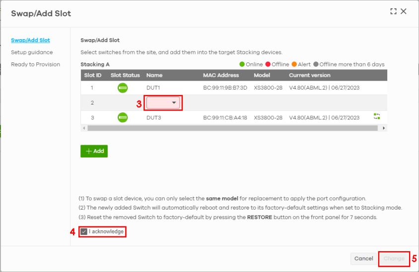
Add a Nebula Device
To add a Nebula Device to the stacking system, do the following:
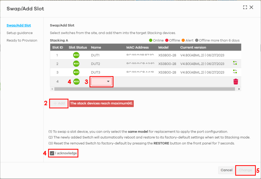
2 On the Swap/Add Slot screen, click + Add to add another Nebula Device to the stacking system.
3 In the Name field, select the Nebula Device in your site to add to the stacking system.
4 When the Slot Status of the new Nebula Device is green, click I acknowledge.
5 Click Change. The Nebula Device will automatically reboot to Cloud Stacking mode. NCC will assign the new Slot ID to the Nebula Device, see the STACK ID LED of the Nebula Device.
6 Update the stacking cable connection onsite. See Hardware Connections (for Stacking) for the steps.
7 Then click Next.
8 Click Provision to apply the site-wide port settings to the new Nebula Device and exit the wizard.
Otherwise, the Nebula Device will restore to its factory-default settings to prevent mis-configurations in NCC. You need to reconfigure the port settings in NCC.
– One or more Nebula Devices in the stacking system are offline
– The Nebula Device’s order of connection do not match the Slot ID configuration in NCC.
After fixing the problem, click Reload to update the stacking status. Then click Provision when all the stacking Nebula Device’s Slot Status shows green with lock icon.
Swap a Nebula Device
Otherwise, after replacing a new Nebula Device on a stacking system, the Nebula Device will restore to its factory-default settings to prevent mis-configurations in NCC. You need to reconfigure the port settings in NCC.
To swap a Nebula Device in the stacking system, do the following:
2 On the Swap/Add Slot screen, select the Nebula Device you want to swap and click the swap icon.
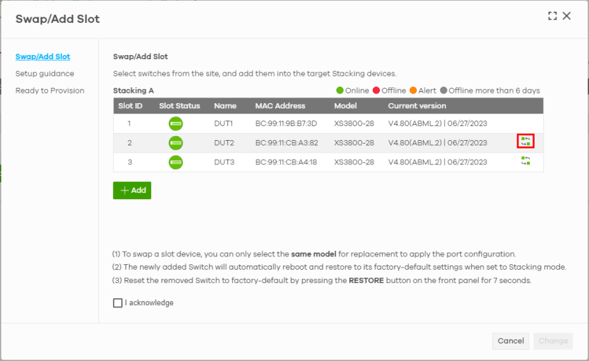
3 In the Name field, select the Nebula Device in your site to swap in the stacking system.
4 When the Slot Status of the new Nebula Device is green, click I acknowledge.
5 Click Change. The new Nebula Device will automatically reboot to Cloud Stacking mode. NCC will assign the previous Slot ID to the new Nebula Device, see the STACK ID LED on the front panel.
6 Update the stacking cable connection onsite. See Hardware Connections (for Stacking) for the steps.
7 Then click Next.

8 Click Provision to apply the site-wide port settings to the new Nebula Device and exit the wizard.

ACL
ACL lets you allow or block traffic going through the Nebula Devices according to the rule settings. Use this screen to configure ACL rules on the Nebula Devices.
Click Site-wide > Configure > Switches > ACL to access this screen.
Site-wide > Configure > Switches > ACL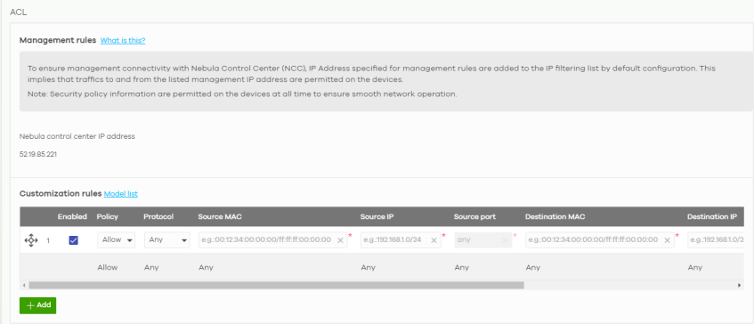
The following table describes the labels in this screen.
Label | Description |
|---|---|
Management rules | The NCC automatically creates rules to allow traffic from/to the Nebula Control Center IP addresses in the list. |
Customization rules | |
 | Click the icon of a rule and drag the rule up or down to change the order. |
Enabled | Select the checkbox to turn on the rule. Otherwise, clear the checkbox to turn off the rule. |
Policy | Select to allow or deny traffic that matches the filtering criteria in the rule. |
Protocol | Select the type of IP protocol used to transport the traffic to which the rule is applied. |
Source MAC | Enter the source MAC address of the packets that you want to filter. |
Source IP | Enter the source IP address of the packets that you want to filter. |
Source port | Enter the source port numbers that defines the traffic type. |
Destination MAC | Enter the destination MAC address of the packets that you want to filter. |
Destination IP | Enter the destination IP address of the packets that you want to filter. |
Destination port | Enter the destination port numbers that defines the traffic type. |
VLAN | Enter the ID number of the VLAN group to which the matched traffic belongs. |
Description | Enter a descriptive name for the rule. |
Delete | Click the delete icon to remove the rule. |
Add | Click this button to create a new rule. |
IP & Routing
This screen enables you to create IP interfaces, static routes, and DHCP option 82 profiles on Nebula Devices in the site. This allows you to do the following:
• Create IP interfaces on a L2 Nebula Device for management or monitoring services, such as IGMP querier, auto PD recovery, ping, and ONVIF discovery.
• Create multiple IP interface on a L3 Nebula Device to route across VLANs.
• Create an IP interface and static route to specify the next hop to a specific destination subnet.
• Add Nebula Device (relay agent) information when forwarding client-originated DHCP packets to a DHCP server. This feature provides additional security when DHCP allocates network IPv4 addresses. This prevents DHCP client requests from untrusted sources.
Click Site-wide > Configure > Switches > IP & Routing to access this screen.
Site-wide > Configure > Switches > IP & Routing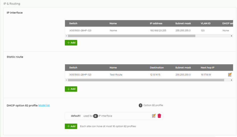
The following table describes the labels in this screen.
Label | Description |
|---|---|
IP interface | |
Switch | This shows the name of the Nebula Device. |
Name | This shows the name of the interface (network) on the Nebula Device. |
IP address | This shows the IP address of the interface (network). |
Subnet mask | This shows the subnet mask of the interface (network). |
VLAN ID | This shows the ID number of the VLAN with which the interface (network) is associated. |
DHCP setting | This shows the type of DHCP service the Nebula Device provides to the network in the site. This shows None when the Nebula Device does not provide any DHCP services. This shows DHCP relay when the Nebula Device routes DHCP requests to one or more DHCP servers you specify. The DHCP servers may be on another network in the site. |
Relay profile | This shows the name of the DHCP option 82 profile that is bound to the IP interface. See Add Option 82 Profile on adding and enabling a DHCP option 82 profile on the IP interface. Otherwise, this shows None. |
 | Click this icon to modify the interface. |
 | Click this icon to delete the interface. |
+ Add | Click this button to create a new interface on a Nebula Device in the site. |
Static route | |
Switch | This shows the name of the Nebula Device. |
Name | This shows the name of the static route. |
Destination | This shows the destination IP address. |
Subnet mask | This shows the IP subnet mask. |
Next hop IP | This shows the IP address of the next-hop gateway or the interface through which the traffic is routed. The gateway is a router or Nebula Device on the same segment as your Security Appliance's interfaces. It helps forward packets to their destinations. |
 | Click this icon to modify the static route. |
 | Click this icon to delete the static route. |
+ Add | Click this button to create a new static route on a Nebula Device in the site. |
DHCP option 82 profile | A DHCP option 82 profile allows the Nebula Device to send additional information (such as the VLAN ID) together with the DHCP requests to the DHCP server. This allows the DHCP server to assign the appropriate IP address according to the VLAN ID. This shows the DHCP option 82 profile that is created on NCC. |
 | Click the edit icon to change the DHCP option 82 profile settings. |
 | Click the remove icon to delete the DHCP option 82 profile. |
+ Add | Click this button to create a new DHCP option 82 profile on a Nebula Device in the site. |
Add IP Interface
Click the + Add button on the Site-wide > Configure > Switches > IP & Routing > IP Interface screen to access this screen.
Site-wide > Configure > Switches > IP & Routing > IP Interface > Add
The following table describes the labels in this screen.
Label | Description |
|---|---|
Switch | Select a Nebula Device in the site on which to create the interface. |
Name | Enter a name of the interface (network) on the Nebula Device. |
Interface IP | Enter the IP address of the interface (network). |
Subnet mask | Enter the subnet mask of the interface (network). |
VLAN | Enter the ID number of the VLAN with which the interface (network) is associated. |
DHCP setting | |
DHCP | Select DHCP Relay if you want the Nebula Device to route DHCP requests to one or more DHCP servers you specify. The DHCP servers may be on another network in the site. Otherwise, select None. |
Relay server 1 | Enter the IPv4 address of a DHCP server for the network in the site. |
Relay server 2 / 3 | These fields are optional. Enter the IP address of another DHCP server for the network in the site. |
Option 82 profile | Select an existing option 82 profile. Alternatively, click Create new profile to go to the Option 82 profile screen to add information such as port, VLAN ID, hostname, and MAC address (in hexadecimal format) to DHCP messages. This allows the DHCP server to assign the appropriate IP address according to the port, VLAN ID, hostname, and MAC address. Go to Add Option 82 Profile for more information. Otherwise, select None. |
Close | Click Close to exit this screen without saving. |
Create | Click Create to save your changes and create the interface. |
Add Static Route
Click the + Add button on the Site-wide > Configure > Switches > IP & Routing > Static Route screen to access this screen.
Site-wide > Configure > Switches > IP & Routing > Static Route > Add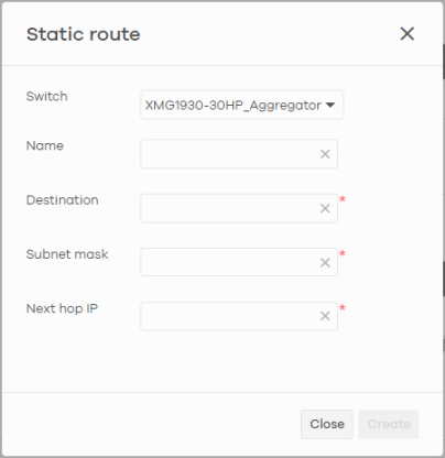
The following table describes the labels in this screen.
Label | Description |
|---|---|
Switch | Select a Nebula Device in the site on which to create the interface. |
Name | Enter a descriptive name for this route. |
Destination | Specifies the IP network address of the final destination. |
Subnet mask | Enter the IP subnet mask. |
Next hop IP | Enter the IP address of the next-hop gateway. |
Close | Click Close to exit this screen without saving. |
Create | Click Create to save your changes and create the static route. |
Add Option 82 Profile
Use this screen to add information such as port, VLAN ID, hostname, and MAC address (in hexadecimal format) to DHCP messages. DHCP servers then create policies that match these new identifiers for DHCP assignment. Click the + Add button on the Site-wide > Configure > Switches > IP & Routing > DHCP option 82 profile screen to access this screen.
Site-wide > Configure > Switches > IP & Routing > DHCP option 82 profile > Add
The following table describes the labels in this screen.
Label | Description |
|---|---|
Profile name | Enter a descriptive name for this profile, up to 64 keyboard characters. |
Circuit-ID | Use this section to configure the Circuit ID sub-option to include information such as port, VLAN ID, and hostname (in hexadecimal format) that is specific to the DHCP relay agent (the Nebula Device). For example: ‘0014000a475331333530string’. Where: • ‘0014’ is the port information, ‘00’ is the slot ID and ‘14’ is the port number • ‘000a’ is the VLAN ID • ‘475331333530’ is the hostname • ‘string’ is the optional string. See String (Optional) for more information. |
Enabled | Select this checkbox to have the Nebula Device add the Circuit ID sub-option to client DHCP requests that it relays to a DHCP server. |
ID | This identifies the row for Circuit-ID sub-option. |
Sub-option | Select the Port option to have the Nebula Device add the port information that the DHCP client connects to. This allows the DHCP server to assign IPv4 addresses to the Nebula Device with the corresponding port information. Select the VLAN ID option to have the Nebula Device add the VLAN ID information to which the port belongs. This allows the DHCP server to assign IPv4 addresses to the Nebula Device with the corresponding VLAN ID. Select the Hostname option to add the system name information to the client DHCP requests that it relays to a DHCP server. This allows the DHCP server to assign IPv4 addresses to the Nebula Device with the corresponding hostname. Otherwise, leave this field blank. |
String (Optional) | Enter an optional string of up to 64 printable ASCII characters that the Nebula Device adds into the client DHCP requests, except the characters inside the square brackets [ ? ], [ | ], [ ' ], [ " ] or [ , ]. |
Remote-ID | Use this section to configure the Remote ID sub-option to include information such as the MAC address (in hexadecimal format) that is specific to the DHCP relay agent (the Nebula Device). For example: ‘bccf4f000001custom’. Where: • ‘bccf4f000001’ is the MAC address • ‘custom’ is the optional string. See String (Optional) for more information. |
Enabled | Select this checkbox to have the Nebula Device append the Remote ID sub-option to the option 82 field of DHCP requests. |
ID | This identifies the row for Remote-ID sub-option. |
Sub-option | Select the MAC option to have the Nebula Device add its MAC address information to the client DHCP requests that it relays to a DHCP server. Otherwise, leave this field blank. |
String (Optional) | Enter an optional string of up to 64 printable ASCII characters that the Nebula Device adds into the client DHCP requests, except the characters inside the square brackets [ ? ], [ | ], [ ' ], [ " ] or [ , ]. |
Close | Click Close to exit this screen without saving. |
Save & Back | Click Save & Back to save your changes and close this screen. |
ONVIF Discovery
IP-based security products use a specific protocol for communication. One of the most common protocols is ONVIF (Open Network Video Interface Forum). ONVIF is a standard interface for interoperability of IP-based security products. When ONVIF is enabled and configured on a Nebula Device, the Nebula Device can obtain information from connected ONVIF-compatible devices, such as a device’s system name and IP address.
In NCC, you can configure ONVIF-compatible Nebula Devices (for example, GS1350) in a site to discover ONVIF-compatible devices in one designated VLAN.

Configuring ONVIF Discovery
Follow these steps to configure ONVIF discovery within a site.
1 Decide on the VLAN ID you want to use for ONVIF discovery within the site. This VLAN is the ONVIF discovery VLAN.
2 Go to Site-wide > Configure > Switches > IP & Routing. For each Nebula Device that you want to enable ONVIF discovery on, add an IP interface for the Nebula Device on the ONVIF discovery VLAN.
3 Go to Site-wide > Configure > Switches > ONVIF discovery. Enable ONVIF discovery, and then set ONVIF VLAN ID to the ID of your ONVIF discovery VLAN.
4 For each Nebula Device that you want to enable ONVIF discovery on, click + Add. Select the Nebula Device, and then enter the ports that you want to listen for ONVIF devices.
ONVIF Discovery Screen
Click Site-wide > Configure > Switches > ONVIF discovery to access this screen.
Site-wide > Configure > Switches > ONVIF discovery
The following table describes the labels in this screen.
Label | Description |
|---|---|
Model list | Click this to view a list of Zyxel Nebula Device models that support ONVIF discovery. |
ONVIF discovery | Enable this to allow ONVIF-compatible Nebula Devices in the site to send ONVIF packets to discover or scan for ONVIF-compatible IP-based security devices. |
ONVIF VLAN ID | Enter the ID number of the VLAN to run ONVIF. You can enter multiple VLAN IDs separated by a comma (,). For example, enter “1,2” for VLAN IDs 1 and 2. |
Switch name | Select the Nebula Device that you want to enable ONVIF discovery on. |
Port list | Enter the port numbers to allow discovery of ONVIF-compatible devices. You can enter multiple ports separated by comma (,) or hyphen (-) without spaces. For example, enter “3-5” for ports 3, 4, and 5. Enter “3,5,7” for ports 3, 5, and 7. |
Description | Enter a descriptive name for this Nebula Device. |
Model | This shows the Nebula Device model. |
 | Click this icon to delete the ONVIF configuration for the Nebula Device. |
+ Add | Click this to configure ONVIF discovery on another Nebula Device in the site. |
Advanced IGMP
A Nebula Device can passively snoop on IGMP packets transferred between IP multicast routers/Nebula Devices and IP multicast hosts to learn the IP multicast group membership. It checks IGMP packets passing through it, picks out the group registration information, and configures multi-casting accordingly. IGMP snooping allows the Nebula Device to learn multicast groups without you having to manually configure them.
The Nebula Device forwards multicast traffic destined for multicast groups (that it has learned from IGMP snooping or that you have manually configured) to ports that are members of that group. IGMP snooping generates no additional network traffic, allowing you to significantly reduce multicast traffic passing through your Nebula Device.
Use this screen to enable IGMP snooping on the Nebula Devices in the site, create IGMP filtering profiles and configure advanced IGMP snooping settings that apply to all ports on the Nebula Device for your IPTV network. Click Site-wide > Configure > Switches > Advanced IGMP to access this screen. You can make adjustments on a per-port basis using the Site-wide > Configure > Switches > Switch ports screen.
Site-wide > Configure > Switches > Advanced IGMP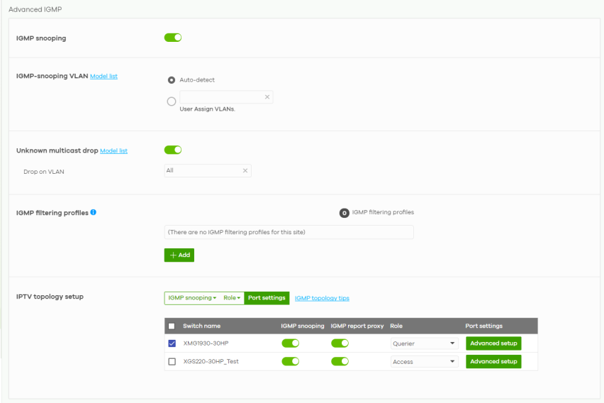
The following table describes the labels in this screen.
Label | Description |
|---|---|
IGMP snooping | Select ON to enable and configure IGMP snooping settings on all Nebula Devices in the site. Select OFF to disable it. |
IGMP-snooping VLAN | Select Auto-detect to have the Nebula Device learn multicast group membership information of any VLANs automatically. Select User Assigned VLANs and enter the VLAN IDs to have the Nebula Device only learn multicast group membership information of the VLANs that you specify. Click Model List to view a list of Zyxel Nebula Device models that do not support this feature. |
Unknown multicast drop | Specify the action to perform when the Nebula Device receives an unknown multicast frame. Select ON to discard the frames. Select OFF to send the frames to all ports. Click Model List to view a list of Zyxel Nebula Device models that do and do not support this feature. |
Drop on VLAN | This allows you to define the VLANs in which unknown multicast packets can be dropped. |
IGMP filtering profiles | An IGMP filtering profile specifies a range of multicast groups that clients connected to the Nebula Device are able to join. You can set the Nebula Device to filter the multicast group join reports on a per-port basis by configuring an IGMP filtering profile and associating a port to the profile. |
 | Click the edit icon to change the profile settings. See Add/Edit IGMP Filtering Profiles. |
 | Click the remove icon to delete the profile. |
+Add | Click this button to create a new profile. See Add/Edit IGMP Filtering Profiles. |
IPTV topology setup The following three buttons are available only when there are multiple Nebula Devices in the site and your administrator account has full access to this screen. | |
IGMP snooping | Select the Nebula Devices you want to configure and click this button to turn on or off IGMP snooping on the selected Nebula Devices. |
Role | Select the Nebula Devices you want to configure and click this button to change the IGMP role of the selected Nebula Devices. |
Port settings | Select the Nebula Devices you want to configure and click this button to open the Port settings screen, where you can change IGMP leave mode and IGMP filtering profile for the ports on the selected Nebula Devices. See IGMP Port Settings. |
IGMP topology tips | Click this to view information about configuring your network and device roles to optimize IPTV performance. |
The following list shows you the IGMP settings for each Nebula Device in the site. | |
Switch Name | This shows the name of the Nebula Device in the site. |
IGMP snooping | Click this to enable IGMP snooping on the Nebula Device. See Advanced IGMP for more information on IGMP snooping. |
IGMP report proxy | Click this to enable IGMP report proxy on the Nebula Device. An IGMP report is generated when monitoring multicast address or membership query. It is highly recommended to disable this in the following conditions: • When the Nebula Device is deployed in a Networked AV environment. A Networked AV environment is specifically designed to simplify configuration and management of the Nebula Device for AVoIP (Audio-Video over Internet Protocol) application. • When the Nebula Device is connected to CPEs (customer premise equipment) that require a specific IPTV source. Some CPEs validate IPTVs based on the source IP and MAC address of their IGMP join request. IGMP report proxy trims down the amount of IGMP join packets and sends its own IGMP join request. |
Role | This shows whether the Nebula Device is acting as an IGMP snooping querier, aggregation Nebula Device or access Nebula Device in the IPTV network. |
Port settings | Click Advanced setup to open the Port settings screen, where you can change IGMP leave mode and IGMP filtering profile for the ports on the Nebula Device. See IGMP Port Settings. |
The following fields display when the IGMP role of a Nebula Device is set to Querier. | |
VLAN | Enter the ID number of the VLAN on which the Nebula Device learns the multicast group membership. |
Querier IP Interface | Enter the IP address of the Nebula Device interface in IGMP querier mode. The Nebula Device acts as an IGMP querier in that network/VLAN to periodically send out IGMP query packets with the interface IP address and update its multicast forwarding table. |
Mask | Enter the subnet mask of the Nebula Device interface in IGMP querier mode. |
 | Click the remove icon to delete the rule. |
Add | Click this button to create a new rule. |
Add/Edit IGMP Filtering Profiles
Use this screen to create a new IGMP filtering profile or edit an existing profile. To access this screen, click the Add button or a profile’s Edit button in the IGMP filtering profiles section of the Site-wide > Configure > Switches > Advanced IGMP screen.
Site-wide > Configure > Switches > Advanced IGMP: Add IGMP Filtering Profile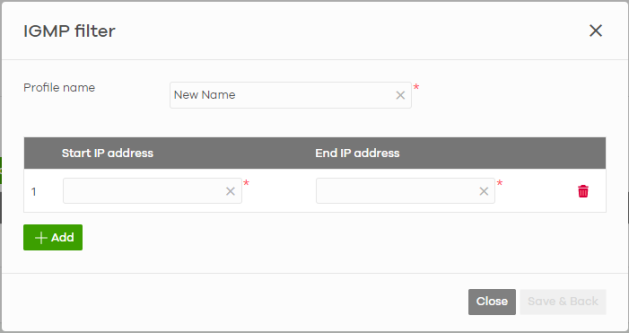
The following table describes the labels in this screen.
Label | Description |
|---|---|
Profile name | Enter a descriptive name for this profile for identification purposes. |
This shows the index number of the rule. | |
Start IP address | Enter the starting multicast IP address for a range of multicast IP addresses that you want to belong to the IGMP filter profile. |
End IP address | Enter the ending multicast IP address for a range of IP addresses that you want to belong to the IGMP filter profile. If you want to add a single multicast IP address, enter it in both the Start IP Address and End IP Address fields. |
 | Click the remove icon to delete the rule. |
+Add | Click this button to create a new rule in this profile. |
Close | Click this button to exit this screen without saving. |
Save & Back | Click this button to save your changes and close the screen. |
IGMP Port Settings
Use this screen to modify the IGMP snooping settings, such as IGMP leave mode and filtering profile for all ports on the Nebula Device. To access this screen, select one or more Nebula Devices and click the Port settings button or click a Nebula Device’s Advanced setup button in the IPTV topology setup section of the Site-wide > Configure > Switches > Advanced IGMP screen.
Site-wide > Configure > Switches > Advanced IGMP: Port settings
The following table describes the labels in this screen.
Label | Description |
|---|---|
Switch name | This shows the name of the Nebula Devices that you select to configure. |
Role | This shows whether the Nebula Devices you selected is an IGMP snooping querier, aggregation Nebula Device or access Nebula Device in the IPTV network. |
Leave mode | Select Immediate Leave to set the Nebula Device to remove this port from the multicast tree immediately when an IGMP leave message is received on this port. Select this option if there is only one host connected to this port. Select Normal Leave or Fast Leave and enter an IGMP normal/fast leave timeout value to have the Nebula Device wait for an IGMP report before the leave timeout when an IGMP leave message is received on this port. You need to specify how many milliseconds the Nebula Device waits for an IGMP report before removing an IGMP snooping membership entry when an IGMP leave message is received on this port from a host. In Normal Leave mode, when the Nebula Device receives an IGMP leave message from a host on a port, it forwards the message to the multicast router. The multicast router then sends out an IGMP Group-Specific Query (GSQ) message to determine whether other hosts connected to the port should remain in the specific multicast group. The Nebula Device forwards the query message to all hosts connected to the port and waits for IGMP reports from hosts to update the forwarding table. In Fast Leave mode, right after receiving an IGMP leave message from a host on a port, the Nebula Device itself sends out an IGMP Group-Specific Query (GSQ) message to determine whether other hosts connected to the port should remain in the specific multicast group. This helps speed up the leave process. |
Maximum group | Select Enable and enter the maximum number of multicast groups this port is allowed to join. Once a port is registered in the specified number of multicast groups, any new IGMP join report received on this port will replace the earliest group entry in the multicast forwarding table. Otherwise, select Disable to turn off multicast group limits. |
IGMP filtering profile | An IGMP filtering profile specifies a range of multicast groups that clients connected to the Nebula Device are able to join. Select the name of the IGMP filtering profile to use for this port. Otherwise, select No Select to remove restrictions and allow the port to join any multicast group. |
Reset | Click this button to return the screen to its last-saved settings. |
Close | Click this button to exit this screen without saving. |
Save | Click this button to save your changes and close the screen. |
Authentication
Use this screen to configure authentication servers and policies to validate access to ports on the Nebula Device using the Nebula cloud authentication server or an external RADIUS server.
NCAS Disconnect Behavior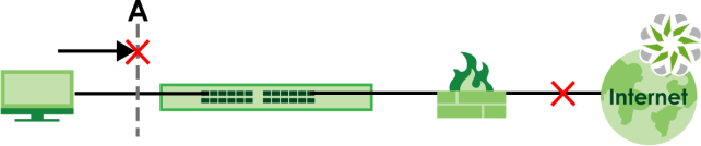
The following figure shows an example Nebula Device with ports enabled for MAC authentication. Clients 1 and 2 (C1, C2) passes MAC authentication (authorized). Client 3 (C3) fails MAC authentication (not authorized).
MAC Authentication Application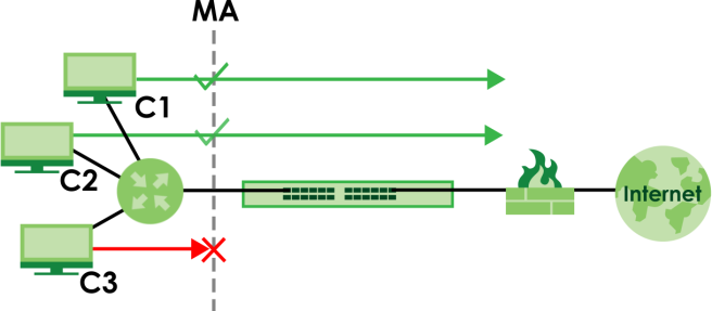
Click Site-wide > Configure > Switches > Authentication to access this screen.
Site-wide > Configure > Switches > Authentication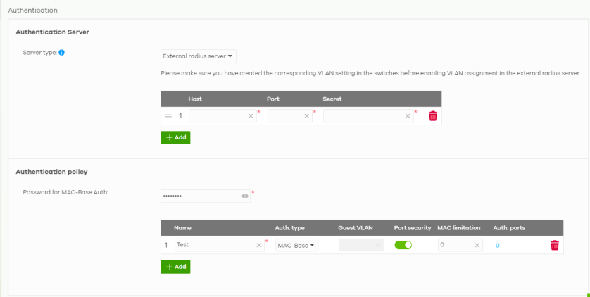
The following table describes the labels in this screen.
Label | Description |
|---|---|
Authentication Server | |
Server type | Select External radius server to have both IEEE 802.1x (WPA-Enterprise) authentication and MAC-based authentication. The Nebula Device sends a request message to a RADIUS server in order to authenticate clients. The administrator must enter the IP address of the RADIUS server. The default port is 1812. Select Nebula cloud authentication to have MAC-based authentication only. The Nebula Device sends HTTPS message to NCAS (Nebula Cloud Authentication Server) to authenticate clients. The default port is 443. See Set Up MAC Authentication With NCAS (for Nebula Switches only) for the steps in setting up MAC authentication with NCAS. Blocked clients do not appear in the Nebula Device MAC address table. The Nebula Device re-authenticates blocked clients when: • 5 minutes after blocked client failed authentication • Blocked client disconnects and reconnects to the Nebula Device port. All network traffic from clients will be denied when the NCAS cannot be reached. |
The following fields appear when you select External radius server as the Server type. | |
 | Click the icon of a rule and drag the rule up or down to change the order. |
Host | Enter the IP address of the external RADIUS server. |
Port | Enter the port of the RADIUS server for authentication (default 1812). |
Secret | Enter a password (up to 32 alphanumeric characters) as the key to be shared between the external RADIUS server and the Nebula Device. |
 | Click the remove icon to delete the entry. |
Add | Click this button to create a new RADIUS server entry. |
Authentication policy | You apply the policy to a port in Site-wide > Configure > Switches > Switch ports: Edit (a selected port). |
Password for MAC-Base Auth | Enter the password the Nebula Device sends along with the MAC address of a client for authentication with the RADIUS server. You can enter up to 32 printable ASCII characters. |
Name | Enter a descriptive name for the policy. |
Auth. type | Select MAC-Base if you want to validate access to the ports based on the MAC address and password of the client. Select 802.1X if you want to validate access to the ports based on the user name and password provided by the client. |
Guest VLAN | A guest VLAN is a pre-configured VLAN on the Nebula Device that allows non-authenticated users to access limited network resources through the Nebula Device. Enter the number that identifies the guest VLAN. |
Port security | Click On to enable port security on the ports. Otherwise, select Off to disable port security on the ports. |
MAC limitation | This field is configurable only when you enable port security. Specify the maximum number of MAC addresses learned on a port. For example, if you set the MAC limitation to 5, then only five clients can be learned on a specific port on any time. |
Auth. ports | This shows the number of the Nebula Device ports to which this policy is applied. |
 | Click the remove icon to delete the profile. |
Add | Click this button to create a new policy. |
PoE Schedules
Use this screen to view and configure Power over Ethernet (PoE) schedules which can be applied to the ports. PoE is enabled at the specified time/date. Click Site-wide > Configure > Switches > PoE schedules to access this screen.
The table shows the name of the existing schedules and the number of ports to which a schedule is applied. Click a schedule’s edit icon to modify the schedule settings or click the Add button to create a new schedule. See Create new schedule.
Site-wide > Configure > Switches > PoE schedules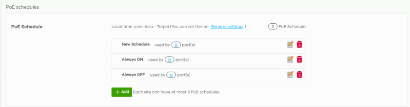
Create new schedule
Click the Add button in the Site-wide > Configure > Switches > PoE schedules screen to access this screen.
Site-wide > Configure > Switches > PoE schedule: Add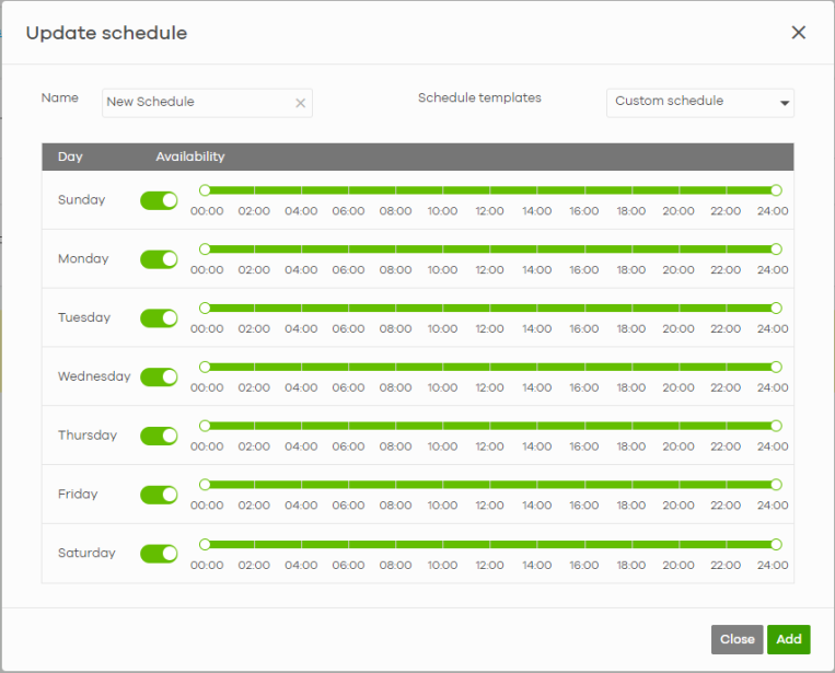
The following table describes the labels in this screen.
Label | Description |
|---|---|
Name | Enter a descriptive name for this schedule for identification purposes. |
Schedule templates | Select a pre-defined schedule template or select Custom schedule and manually configure the day and time at which PoE is enabled. |
Day | This shows the day of the week. |
Availability | Click On to enable PoE at the specified time on this day. Otherwise, select Off to turn PoE off on the day and at the specified time. Specify the hour and minute when the schedule begins and ends each day. |
Close | Click this button to exit this screen without saving. |
Add | Click this button to save your changes and close the screen. |
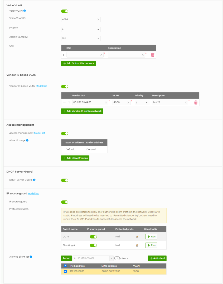
Switch Settings
Use this screen to configure global Nebula Device settings, such as (R)STP, QoS, port mirroring, voice VLAN, DHCP server guard, and IP source guard.
Click Site-wide > Configure > Switches > Switch settings to access this screen.
Site-wide > Configure > Switches > Switch settings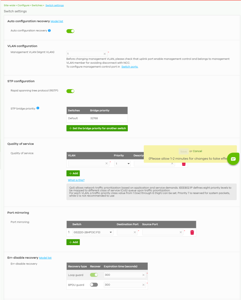
The following table describes the labels in this screen.
Label | Description |
|---|---|
Auto configuration recovery | |
Auto configuration recovery | When On, connectivity check to NCC is done 5 minutes after any configuration change. If an NCC connection problem is detected, the Nebula Device will return to its last saved custom default configuration. The Nebula Device will be locked by NCC and the banner N Switches are currently protected by Auto Configuration Recovery will be displayed. Otherwise, the latest configuration will be saved as the new custom default configuration. |
VLAN configuration | |
Management VLAN (Mgmt VLAN) | Enter the VLAN identification number associated with the Nebula Device IP address. This is the VLAN ID of the CPU and is used for management only. The default is "1". All ports, by default, are fixed members of this "management VLAN" in order to manage the device from any port. If a port is not a member of this VLAN, then users on that port cannot access the device. To access the Nebula Device make sure the port that you are connected to is a member of Management VLAN. Before changing the management VLAN for an uplink port, check the following to avoid disconnection with NCC: • Management Control is enabled in Site-wide > Configure > Switches > Switch ports • The uplink port belongs to the management VLAN in Site-wide > Configure > Switches > Switch ports: PVID. |
STP configuration | |
Rapid spanning tree protocol (RSTP) | Select On to enable RSTP on the Nebula Device. Otherwise, select Off. |
STP bridge priority | Bridge priority is used in determining the root Nebula Device, root port and designated port. The Nebula Device with the highest priority (lowest numeric value) becomes the STP root Nebula Device. If all Nebula Devices have the same priority, the Nebula Device with the lowest MAC address will then become the root Nebula Device. The lower the numeric value you assign, the higher the priority for this bridge. Click Set the bridge priority for another switch to create a new entry. Select the Nebula Devices for which you want to configure the bridge priority, and select a value from the drop-down list box. |
Quality of service | |
Quality of service | Enter a VLAN ID and select the priority level that the Nebula Device assigns to frames belonging to this VLAN. Enter a descriptive name for the QoS (Quality of Service). Click Add to create a new entry. |
Port mirroring | |
Port mirroring | Click Add to create a new entry. Select the Nebula Device/stacking system for which you want to configure port mirroring, specify the destination port you copy the traffic to in order to examine it in more detail without interfering with the traffic flow on the original ports, and also enter the source port on which you mirror the traffic. If the port is on a stacking Nebula Device, enter the slot ID/port number to specify the destination and source ports. For example, to specify slot ID 2 port 20 in a stacking system, enter ‘2/20’. |
Err-disable recovery | |
Err-disable recovery | Enter the number of seconds (from 30 to 86400) to wait to activate a port or allow specific packets on a port, after the loop guard / BPDU guard error was gone. The loop guard feature shuts down a port if it detects that packets sent out on that port loop back to the Nebula Device. The BPDU guard feature allows you to prevent any new STP-aware (Spanning Tree Protocol) switch from connecting to an existing network and causing STP topology changes in the network. If there is any BPDU detected on the ports on which BPDU guard is enabled, the Nebula Device disables the ports automatically. • Loop guard recovery is always enabled. • Click the switch to enable BPDU guard recovery. Default setting is disabled. • The range of Expiration time (seconds) for both Loop guard recovery and BPDU guard recovery is 30 to 86400. |
Voice VLAN | |
Voice VLAN | Select On to enable the Voice VLAN feature on the Nebula Device. Otherwise, select Off. It groups the voice traffic with defined priority into an assigned VLAN which enables the separation of voice and data traffic coming into the Nebula Device port. |
Voice VLAN ID | Enter a VLAN ID number. |
Priority | Select the priority level of the Voice VLAN from 1 to 6. |
Assign VLAN by | Select how the Nebula Device assigns ports connected to VoIP devices to the Voice VLAN. OUI (Organizationally Unique Identifier): The Nebula Device assigns a port connected to a VoIP device to the Voice VLAN if the connected device’s OUI matches any OUI in the list. LLDP-MED: The Nebula Device assigns a port connected to a VoIP device to the voice VLAN if the connected device is identified as a VoIP device using the LLDP-MED protocol. |
OUI | This field appears when you select OUI in the Assign VLAN by field. Click Add OUI on this network to add an OUI and a description for the OUI. An Organizationally Unique Identifier identifies a manufacturer. Typically, a device’s OUI is the first three octets of the device’s MAC address. For example, if you have an IP phone from Company A with MAC address 00:0a:95:9d:68:16, you can enter OUI 00:0a:95 to match all devices from Company A. |
DSCP | This field appears when you select LLDP-MED in the Assign VLAN by field. Enter the Differentiated Services Code Point (DSCP) value for traffic on the voice VLAN. The value is defined from 0 through 63, and 0 is the default. |
Vendor ID based VLAN | |
Vendor ID based VLAN | Select On to enable the Vendor ID based VLAN feature on the Nebula Device. Otherwise, select Off. Click the Add Vendor-ID on this network button to define the vendor MAC address OUI, assign to which VLAN, and set the priority. Enter a descriptive name for the Vendor ID based VLAN. Enter up to 64 characters for this field including special characters inside the square quotes [~!@#$%^&*()_+{}|:”<>–=[]\;’,/ ]. |
Access management | |
Access management | Select On to enable the access management feature on the Nebula Device. Otherwise, select Off. |
Allow IP range | Click the Add allow IP range button to set the connected devices’ starting and ending IP addresses that will be allowed to access the Nebula Devices through telnet, SSH, HTTP, HTTPS, and FTP. |
DHCP Server Guard | |
DHCP Server Guard | Select On to enable the DHCP server guard feature on the Nebula Device in order to prevent illegal DHCP servers. Only the first DHCP server that assigned the Nebula Device IP address is allowed to assign IP addresses to devices in this management VLAN. Otherwise, select Off to disable it. |
IP source guard | |
IP source guard | Select On to enable IP source guard protection. IP source guard uses a binding table to distinguish between authorized and unauthorized DHCP and ARP packets in your network. When the client does not exist in the binding table, the client is unauthorized and traffic will be blocked. To successfully access the network: • Client with static IP address will need to be added to the Allowed client list • Client with dynamic IP address will need to get their IP address from an authorized DHCP server. |
Protected switch | This shows the Nebula Device/stacking system. • Select On to enable IP source guard protection on the Nebula Device/stacking system. Then click Save. • Click the edit icon to go to Site-wide > Configure > Switches > Switch ports to configure Protected ports (see Switch Ports for more information). • Click Run to display a pop-up window showing the current client table. • Select the DHCP-snooping or Block entries and click Transfer to add these to the allowed client list. Then click Save. |
Allowed client list | This allows the administrator to define a set of clients. Click Add client to define the IPv4 address, MAC address, and VLAN of the static client. A previous entry will be overwritten when you enter a duplicate MAC address and VLAN ID. Click Action > Edit to modify the static client entry. Then click Update. The MAC address and VLAN ID will appear in red when you enter a duplicate entry. Click Action > Delete to remove the static client entry. Click Save to activate the settings. |