Configure
Use the Configure menus to configure interface addressing, firewall, site-to-site VPN, captive portal, traffic shaping, authentication server, IPTV, and other gateway settings for the Nebula Device of the selected site.
Interface
Use this screen to configure network interfaces on the Nebula Device. An interface consists of a VLAN ID and an IP address, plus other configuration settings.
To access this screen, click Site-wide > Configure > Security router > Interface.
Site-wide > Configure > Security router > Interface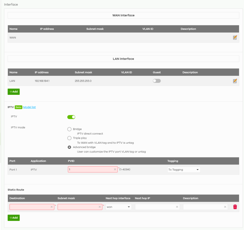
The following table describes the labels in this screen.
Label | Description |
|---|---|
Interface WAN Interface | |
Name | This field is read-only. |
IP address | This shows the IP address for this interface. |
Subnet mask | This shows the subnet mask of this interface in dot decimal notation. The subnet mask indicates what part of the IP address is the same for all computers in the network. |
VLAN ID | This shows the VLAN ID. This 12-bit number uniquely identifies each VLAN. Allowed values are 2 – 4094. (0, 1 and 4095 are reserved.) |
Description | This shows the description of this interface. |
 | Click the edit icon to modify this interface. |
LAN Interface | |
Name | This field is read-only if you are editing an existing LAN interface. Specify a name for the interface. The format of interface names is strict. Each name consists of 2 – 4 letters (interface type), followed by a number (x). For most interfaces, x is limited by the maximum number of the type of interface. For VLAN interfaces, x is defined by the number you enter in the VLAN name field. For example, VLAN interfaces are vlan0, vlan1, vlan2, and so on. |
IP address | This is the IP address for this interface. |
Subnet mask | This is the subnet mask of this interface in dot decimal notation. The subnet mask indicates what part of the IP address is the same for all computers in the network. |
VLAN ID | This shows the VLAN ID. This 12-bit number uniquely identifies each VLAN. Allowed values are 2 – 4094. (0, 1 and 4095 are reserved.) |
Guest | Click the switch to the right to configure this interface as a Guest interface. Client devices connected to this Guest interface have Internet access but cannot access a non-guest interface. Alternatively, click the switch to the left to disable Internet access for client devices connected to this Guest interface. |
Description | This shows the description of this interface. |
 | Click the edit icon to modify it. |
Add | Click this button to create a new LAN interface. |
IPTV | The following fields are available only when IPTV is enabled. |
IPTV | Click the switch to the right to turn on the IPTV (Internet Protocol Television) service. IPTV is a service that delivers video traffic over an Internet Protocol (IP) network connection. |
IPTV mode | Select Bridge mode when your IPTV service provider does not use a VLAN tag for the IPTV multicast traffic. Select Triple play mode when your IPTV service provider uses a VLAN tag for the IPTV multicast traffic. The Nebula Device will tag outgoing traffic from port 1 with the IPTV service provider VLAN tag. Select Advanced bridge mode when a manageable Switch is connected to port 1 of the Nebula Device for IPTV traffic and Internet access. Make sure to assign a different VLAN ID for IPTV traffic. |
Port 1 | This field is available only when the IPTV mode is set to Bridge. Multicast traffic from the IPTV server on the Internet goes through the Nebula Device to port 1 only. This field is read-only. |
VLAN ID | This field is available only when the IPTV mode is set to Triple play. Configure the IPTV VLAN ID, for example 4081. The Nebula Device will tag traffic from port 1 with the IPTV VLAN tag going to the Internet. Allowed values are 2 – 4094. (0, 1 and 4095 are reserved.) |
Priority (802.1P) | This field is available only when the IPTV mode is set to Triple play. Enter the 802.1p number your IPTV service provider gave you to prioritize IPTV traffic. “0” is the lowest priority level and “7” is the highest. |
Port | This field is available only when the IPTV mode is set to Advanced bridge. Multicast traffic from the IPTV server on the Internet goes through the Nebula Device to port 1 only. This field is read-only. |
Application | This field is available only when the IPTV mode is set to Advanced bridge. Multicast traffic from the IPTV server on the Internet goes through the Nebula Device. This field is read-only. |
PVID | This field is available only when the IPTV mode is set to Advanced bridge. Configure the IPTV VLAN ID, for example 4081. The Nebula Device will tag traffic from port 1 with the IPTV VLAN tag going to the Internet. Allowed values are 2 – 4094. (0, 1 and 4095 are reserved.) When the multicast traffic is through the WAN (Internet) then it is untagged. |
Tagging | This field is available only when the IPTV mode is set to Advanced bridge. Select Tx Tagging for the connected manageable Switch to forward IPTV-tagged traffic to the subscribers. If you do not have a connected manageable Switch, select Tx Untag or select Bridge mode in IPTV mode. |
Static Route | |
Destination | Enter the destination IP address. |
Subnet mask | Enter an IP subnet mask. The route applies to all IP addresses in the subnet. |
Next hop interface | Select the interface you want to send all traffic to. |
Next hop IP | Enter the IP address of the next-hop gateway. |
Description | This is the descriptive name of the static route, maximum up to 255 alphanumeric characters. |
 | Click this icon to modify a static route. |
 | Click this icon to remove a static route. |
Add | Click this button to create a new static route, maximum up to 20. |
WAN Interface Configuration
Click the Edit button in the WAN Interface section to open the Security router > Configure > Interface > WAN interface configuration screen.
Site-wide > Configure > Security router > Interface > WAN interface configuration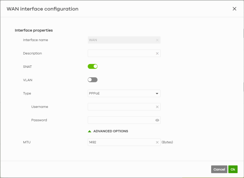
The following table describes the labels in this screen.
label | description |
|---|---|
Interface properties | |
Interface name | This field is read-only. |
Description | Enter a description of the WAN interface here. You can use alphanumeric and ()+/:=?!*#@$_%– characters, and it can be up to 512 characters long. |
SNAT | Select this to enable SNAT. When enabled, the Nebula Device rewrites the source address of packets being sent from this interface to the interface's IP address. |
VLAN | Select On to enable the VLAN feature on the WAN interface. Otherwise, select Off. |
VLAN ID | Enter the VLAN ID. This 12-bit number uniquely identifies each VLAN. Allowed values are 2 – 4094. (0, 1 and 4095 are reserved.) |
Type | Select the type of interface to create. DHCP: The interface will automatically get an IP address and other network settings from a DHCP server. Static: You must manually configure an IP address and other network settings for the interface. PPPoE: The interface will authenticate with an Internet Service Provider, and then automatically get an IP address from the ISP's DHCP server. You can use this type of interface to connect to a DSL modem. PPPoE with static IP: Assign a static IP address to the WAN interface and your WAN interface is getting an Internet connection from a PPPoE server. |
IP address assignment | These fields are displayed if you select Static. |
IP address | Enter the static IP address of this interface. |
Subnet mask | Enter the subnet mask for this interface’s IP address. |
Default gateway | Enter the IP address of the Nebula Device through which this interface sends traffic. |
First DNS server | Enter a DNS server's IP address. The Domain Name System (DNS) maps a domain name to an IP address and vice versa. The Nebula Device uses the first and second DNS servers, in that order to resolve domain names for VPN, DDNS and the time server. Leave the field blank if you do not want to configure DNS servers. |
Second DNS server | Enter the IP address of another DNS server. This field is optional. |
These fields are displayed if you selected PPPoE or PPPoE with static IP. | |
Username | Enter the user name provided by your ISP. You can use up to 31 alphanumeric characters and the underscore. Spaces are not allowed. |
Password | Enter the password provided by your ISP. You can use up to 64 alphanumeric characters and the underscore. Spaces are not allowed. |
IP address assignment | |
IP address | Enter the static IP address of this interface. |
DNS server | Enter a DNS server's IP address. The Domain Name System (DNS) maps a domain name to an IP address and vice versa. The Nebula Device uses the first and second DNS servers, in that order to resolve domain names for VPN, DDNS and the time server. Leave the field blank if you do not want to configure DNS servers. |
ADVANCED OPTIONS | |
MTU | Maximum Transmission Unit. Enter the maximum size of each data packet, in bytes, that can move through this interface. If a larger packet arrives, the Nebula Device divides it into smaller fragments. Allowed values are 1280 – 1500 for static IP/DHCP; 1280 – 1492 for PPPoE/PPPoE with static IP. |
DHCP option 60 | This field is available only when the Type is set to DHCP. DHCP option 60 is used by the Nebula Device for identification to the DHCP server using the VCI (Vendor Class Identifier) on the DHCP server. The Nebula Device adds it in the initial DHCP discovery message that a DHCP client broadcasts in search of an IP address. The DHCP server can assign different IP addresses or options to clients with the specific VCI or reject the request from clients without the specific VCI. Enter a string using up to 63 of these characters [a–z A–Z 0–9 !\"#$%&\'()*+,-./:;<=>?@\[\\\]^_`{}] to identify this Nebula Device to the DHCP server. For example, Zyxel-TW. |
Cancel | Click Cancel to exit this screen without saving. |
OK | Click OK to save your changes. |
LAN Interface Configuration
Click the Add button or click the Edit button in the LAN interface section to open the Site-wide > Configure > Security router > Interface > LAN interface configuration screen.
Site-wide > Configure > Security router > Interface > LAN interface configuration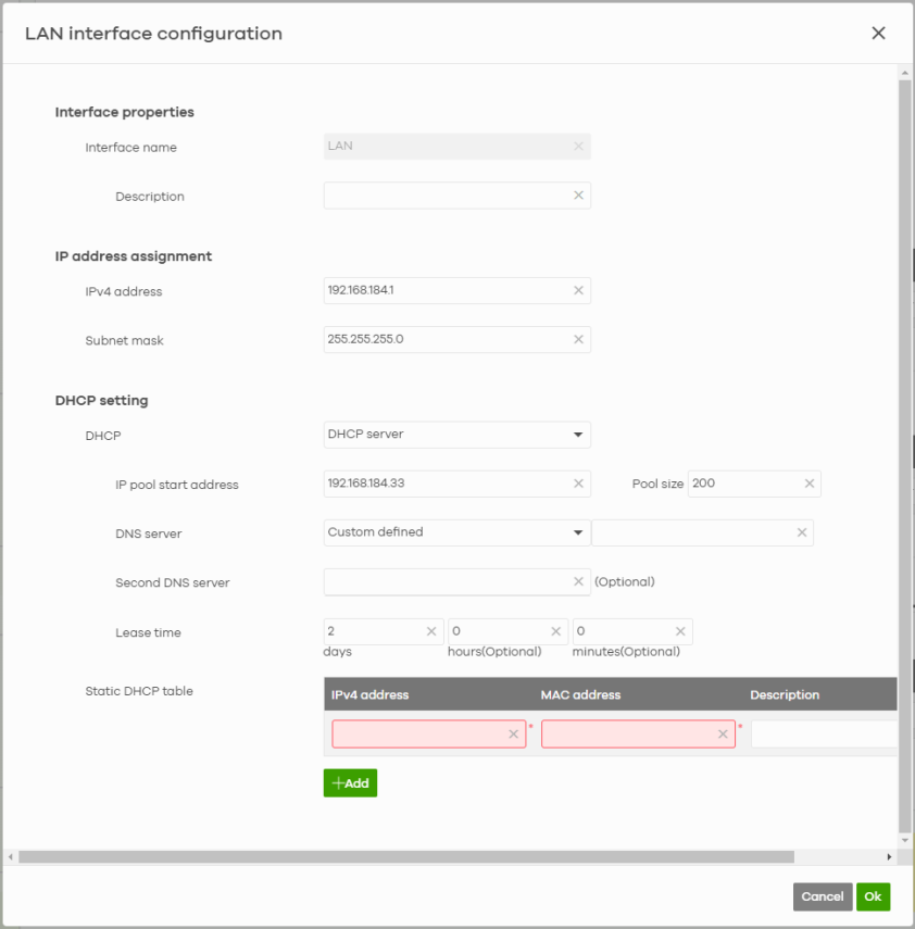
The following table describes the labels in this screen.
label | description |
|---|---|
Interface properties | |
Interface name | Specify a name for the LAN interface. Enter up to 15 alphanumeric characters. • ethernet • ppp • vlan • bridge • virtual • wlan • cellular • aux • tunnel • status • summary • all |
Description | Enter a description of the LAN interface here. You can use alphanumeric and ()+/:=?!*#@$_%– characters, and it can be up to 512 characters long. |
IP address assignment | |
IPv4 address | Enter the IPv4 address for this interface. |
Subnet mask | Enter the subnet mask of this interface in dot decimal notation. The subnet mask indicates what part of the IP address is the same for all computers in the network. |
DHCP setting DHCP | Select what type of DHCP service the Nebula Device provides to the network. Choices are: None – the Nebula Device does not provide any DHCP services. There is already a DHCP server on the network. DHCP relay – the Nebula Device routes DHCP requests to one or more DHCP servers you specify. The DHCP servers may be on another network. DHCP server – the Nebula Device assigns IP addresses and provides subnet mask, gateway, and DNS server information to the network. The Nebula Device is the DHCP server for the network. |
This field appear if the Nebula Device is a DHCP Relay. | |
DHCP server | Enter the IP address of a DHCP server for the network. |
These fields appear if the Nebula Device is a DHCP Server. | |
IP pool start address | Enter the IP address from which the Nebula Device begins allocating IP addresses. If you want to assign a static IP address to a specific computer, use the Static DHCP table. If this field is blank, the Pool size must also be blank. In this case, the Nebula Device can assign every IP address allowed by the interface’s IP address and subnet mask, except for the first address (network address), last address (broadcast address) and the interface’s IP address. |
DNS server | Specify the IP addresses of up to two DNS servers for the DHCP clients to use. Use one of the following ways to specify these IP addresses. Custom defined – enter a static IP address. From ISP – select the DNS server that another interface received from its DHCP server. This Router – the DHCP clients use the IP address of this interface and the Nebula Device works as a DNS relay. |
Second DNS server | Enter the IP address of another DNS server. This field is optional. |
Lease time | Specify how long each computer can use the information (especially the IP address) before it has to request the information again. days, hours, and minutes (Optional) – enter how long IP addresses are valid. |
Static DHCP table | Configure a list of static IP addresses the Nebula Device assigns to computers connected to the interface. Otherwise, the Nebula Device assigns an IP address dynamically using the interface’s IP pool start address and Pool size. |
IPv4 address | Enter the IPv4 address to assign to a device with this entry’s MAC address. |
MAC address | Enter the MAC address to which to assign this entry’s IP address. |
Description | Enter a description to help identify this static DHCP entry. You can use alphanumeric and ()+/:=?!*#@$_%– characters, and it can be up to 60 characters long. |
 | Select an entry in this table and click this to delete it. This will also remove the client information on the Site-wide > Clients > Client list. |
+Add | Click this to create an entry in the Static DHCP table. This will also add the client reserve IP policy on the Site-wide > Clients > Client list. |
Cancel | Click Cancel to exit this screen without saving. |
OK | Click OK to save your changes. |
IPTV Scenarios
The Nebula Device forwards IPTV multicast traffic to IPTV subscribers connected to port 1. The following are the supported IPTV scenarios:
• Your IPTV service provider does not use a VLAN tag for the IPTV multicast traffic.
• Your IPTV service provider uses a VLAN tag for the IPTV multicast traffic.
• Your IPTV service provider uses a VLAN tag for the IPTV multicast traffic and you have a VLAN-aware Switch in your network connected to port 1 of the Nebula Device.
• The Set Top Box tags IPTV traffic with a VLAN tag for IPTV multicast traffic. You also have a VLAN-aware Switch connected to port 1 of the Nebula Device.
IPTV Scenario Configurations
IPTV Bridge (IPTV Direct)
In this scenario, your IPTV service provider does not use a VLAN tag for the IPTV multicast traffic. Connect the IPTV subscriber to port 1 (P1) of the Nebula Device (Z). IPTV multicast traffic from the IPTV server on the Internet goes through the Nebula Device (Z) to this port (P1) only.
IPTV Bridge Application 
On NCC, do the following:
1 Go to Site-wide > Configure > Security router > Interface.
2 Click the IPTV switch to the right.
3 Select Bridge in IPTV mode.
Site-wide > Configure > Security router > Interface: Bridge Mode 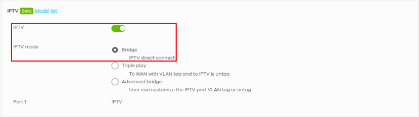
IPTV Triple Play (IPTV with VLAN Tag)
In this scenario, your IPTV service provider uses a VLAN tag for the IPTV multicast traffic. The Nebula Device will tag outgoing traffic from port 1 (P1) with the IPTV service provider VLAN tag that you configured in NCC.
Configure an IPTV VLAN ID, for example 4081, on the Nebula Device (Z), so that the Nebula Device (Z) will tag traffic from port 1 (P1) with the IPTV VLAN tag going to the Internet.
In the following figure, IPTV-T is the IPTV service provider VLAN tag.
If your IPTV service provider gave you an 801.1p number to prioritize IPTV traffic, you may also configure it in the Nebula Device (Z).
IPTV Triple Play Application 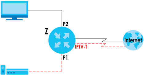
On NCC, do the following:
1 Go to Site-wide > Configure > Security router > Interface.
2 Click the IPTV switch to the right.
3 Select Triple Play in IPTV mode.
4 Enter 4081 in VLAN ID.
5 Select 1 in Priority.
Site-wide > Configure > Security router > Interface: Triple Play Mode 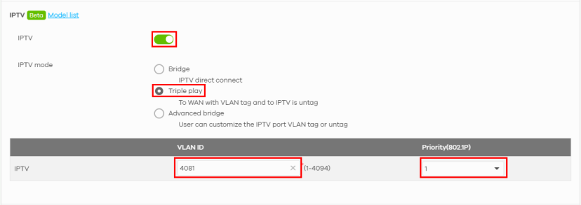
IPTV Advanced VLAN 1
In this scenario, your IPTV service provider uses a VLAN tag for the IPTV multicast traffic and you have a VLAN-aware Switch (S) in your network connected to port 1 (P1) of the Nebula Device. For this example scenario, connect the IPTV subscribers to a VLAN-aware Switch (S) that is connected to port 1 (P1) of the Nebula Device (Z).
Then make the following configurations:
• Configure the VLAN-aware Switch (S) to tag egress (outgoing) traffic going to port 1 (P1) on the Nebula Device (Z) with the IPTV service provider VLAN tag.
• Configure the Nebula Device (Z) to allow TX Tagging for incoming tagged traffic coming from the Switch and going to the Internet.
In the following figure, IPTV-T is the IPTV service provider VLAN tag.
If your IPTV service provider gave you an 801.1p number to prioritize IPTV traffic, you may also configure it in the Nebula Device (Z).
IPTV Advanced VLAN 1 Application 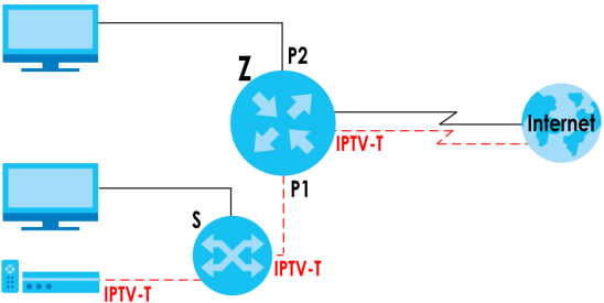
On NCC, do the following:
1 Go to Site-wide > Configure > Security router > Interface.
2 Click the IPTV switch to the right.
3 Select Advanced bridge in IPTV mode.
4 Enter 4081 in PVID.
5 Select TX Tagging in Tagging.
Site-wide > Configure > Security router > Interface: Advanced VLAN 1 
IPTV Advanced VLAN 2
In this scenario, the Set Top Box (STB) tags IPTV traffic with a VLAN tag for IPTV multicast traffic. You also have a VLAN-aware Switch (S) connected to port 1 (P1) of the Nebula Device (Z). For this example scenario, connect the IPTV subscribers to a VLAN-aware Switch (S) that is connected to port 1 (P1) of the Nebula Device (Z).
Then make the following configurations:
• Configure the VLAN-aware Switch (S) to forward IPTV-tagged traffic coming from the STB subscribers and going to the Switch (S).
• Configure the Nebula Device (Z) to also allow TX Tagging for tagged traffic coming from the Switch and going to the Internet.
In the following figure, IPTV-T is the IPTV service provider VLAN tag.
If your IPTV service provider gave you an 801.1p number to prioritize IPTV traffic, you may also configure it in the Nebula Device (Z).
IPTV Advanced VLAN 2 Application 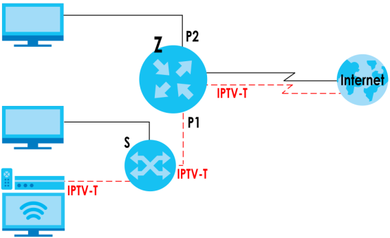
On NCC, do the following:
1 Go to Site-wide > Configure > Security router > Interface.
2 Click the IPTV switch to the right.
3 Select Advanced bridge in IPTV mode.
4 Enter 4081 in PVID.
5 Select TX Tagging in Tagging.
Site-wide > Configure > Security router > Interface: Advanced VLAN 2 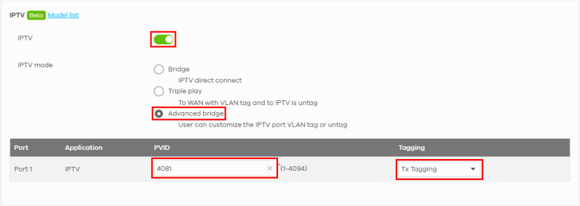
Threat Management
Use this screen to enable the threat management categories such as:
• Ransomware and malware prevention that protects LAN clients from accessing or downloading harmful web contents.
• Intrusion blocker that prevents personal data theft in your network.
• Dark Web blocker that prevents unauthorized access from TOR proxies to the LAN clients.
• Stop mail fraud and phishing that blocks access by your LAN clients to phishing websites and SPAM URLs.
• Ads blocker that prevents access to websites containing annoying advertisements with links to harmful programs.
• VPN proxy blocker that prevents LAN clients connected to the Nebula Device from sending personal data to a cybercriminal’s VPN gateway.
You can also configure the following:
• Up to 50 exception list, using the Nebula Device connected client device’s name or IP address
• Up to 50 allowed domain name list
• Up to 50 blocked domain name list.
Click Site-wide > Configure > Security router > Threat management to access this screen.
Site-wide > Configure > Security router > Threat management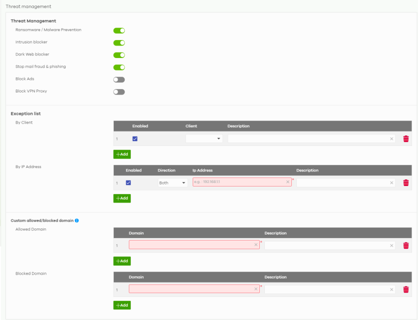
The following table describes the labels in this screen.
Label | Description |
|---|---|
Threat management | |
Ransomware / Malware | Ransomware and malware prevention protects the LAN clients connected to the Nebula Device from accessing or downloading harmful web content. These contents may contain files that could harm your operating system and personal files. Click the switch to enable ransomware/malware protection on the Nebula Device. |
Intrusion blocker | Intrusion blocker prevents cybercriminals from harming, spying, or stealing personal data in your network. Click the switch to enable intrusion blocker protection on the Nebula Device. |
Dark Web blocker | The Dark Web is an anonymous network accessed by browsers such as TOR. The purpose of the Dark Web is to enable anonymous access to content and prevent the identification of both the request and destination. The dark web blocker prevents unauthorized access from TOR proxies to the LAN clients connected to the Nebula Device. Click the switch to enable dark web blocker protection on the browsers of LAN clients connected to the Nebula Device. |
Stop mail fraud & phishing | Mail fraud and phishing sites protection blocks access by your LAN clients to phishing websites and spam URLs. Click the switch to enable mail fraud and phishing protection on the browsers of LAN clients connected to the Nebula Device. |
Block Ads | Ad blocking or ad filtering prevents exposure to websites containing advertisements with links to harmful programs. Click the switch to enable ads blocker protection on the browsers of LAN clients connected to the Nebula Device. |
Block VPN Proxy | VPN proxy blocker prevents the LAN clients connected to the Nebula Device from sending personal data to a cybercriminal’s VPN gateway. Click the switch to enable VPN proxy blocker protection on the browsers of LAN clients connected to the Nebula Device. |
Exception list | Both wired and WiFi LAN clients connected to the Nebula Device in this list will bypass the threat management category check. |
By Client | Enabled – Select this option to turn on this client exception profile. This allows both wired and WiFi LAN clients connected to the Nebula Device to bypass the threat management category check. Select the Client from the drop-down list. See WiFi Client Details and Wired Client Details for more information on WiFi and wired clients. Enter a Description of the allowed client. You can use alphanumeric and ()+/:=?!*#@$_%- characters, and it can be up to 512 characters long. |
 | Click this icon to remove the client exception profile. |
Add | Click this to create a client exception profile. |
By IP Address | Enabled – Select this option to turn on this IPv4 address exception profile. This allows the client with this IPv4 address to bypass the threat management category check. Direction – Select Both to allow incoming/outgoing packets to/from the Nebula Device that match this IPv4 address. Select Source to allow incoming packets to the Nebula Device that match this IPv4 address. Select Destination to allow outgoing packets from the Nebula Device that match this IPv4 address. Add the IP Address that the Nebula Device will allow incoming and/or outgoing packets. Enter a description of the allowed IPv4 address. The description can be up to 512 characters long. |
 | Click this icon to remove the IPv4 address exception profile. |
Add | Click this icon to create an IPv4 address exception profile. |
Custom allowed/blocked domain | Create a list of host names to allow access to, or block access to, regardless of their content rating. |
Allowed Domain | If you want to access any site, regardless of their content rating, add them to this list. Domain – Enter the host name, such as www.good-site.com into this text field. Do not enter the complete URL of the site – that is, do not include “http://”. All sub-domains are allowed. For example, entering “zyxel.com” also allows “www.zyxel.com”, “partner.zyxel.com”, “press.zyxel.com”, and so on. You can also enter just a top level domain. For example, enter .com to allow all .com domains. Use up to 127 characters (0–9 a–z). The casing does not matter. Enter a Description of the allowed domain. You can use alphanumeric and ()+/:=?!*#@$_%- characters, and it can be up to 60 characters long. Click Add to create a domain name profile. |
Blocked Domain | If you want to block specific sites, regardless of their content rating, add them to this list. Domain – Enter the host name, such as www.bad-site.com into this text field. Do not enter the complete URL of the site – that is, do not include “http://”. All sub-domains are also blocked. For example, entering “bad-site.com” also blocks “www.badsite.com”, “partner.bad-site.com”, “press.bad-site.com”, and so on. You can also enter just a top level domain. For example, enter .com to block all .com domains. Enter a Description of the blocked domain. You can use alphanumeric and ()+/:=?!*#@$_%- characters, and it can be up to 60 characters long. Click Add to create a domain name profile. |
Traffic Management
Application management allows you to manage the use of various applications on the network. Content Filter allows you to control access to specific web sites or web content.
Click Site-wide > Configure > Security router > Traffic management to access this screen. Use this screen to control application usage and configure content filter.
Site-wide > Configure > Security router > Traffic management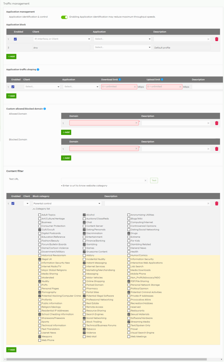
The following table describes the labels in this screen.
Label | Description |
|---|---|
Application management | |
Application identification & control | Click this to enable the Nebula Device to control usage of applications for a client or all clients. When disabled: • the Security router network applications widget in the Site-wide > Dashboard screen will show Application monitor disabled • the Site-wide > Applications usage screen will show Application identification is turned off. |
Application block | |
Enabled | Select the checkbox to turn on the rule. Otherwise, clear the checkbox to turn off the rule. |
Client | Select the client, or enter a single IP address (LAN interface) or IPv4 CIDR (for example, 192.168.1.1/24) to which this rule applies. Then press Enter or click + Add new. Or, select Any to apply the rule to all clients. |
Application | Select All or select an application to apply the rule. |
Description | Enter a description for this profile. The description can be up to 512 characters long. |
 | Click this icon to remove the entry. |
Add | Click this button to create up to five application management profiles. |
Application traffic shaping | |
Enabled | Select the checkbox to turn on the rule. Otherwise, clear the checkbox to turn off the rule. If there is a lock icon, go to the Site-wide > Applications usage screen to change the maximum downstream/upstream bandwidth. See Applications Usage for more information. |
Client | Select the client, or enter a single IP address (LAN interface) or IPv4 CIDR (for example, 192.168.1.1/24) to which this rule applies. Then press Enter. Or, select Any to apply the rule to all clients. |
Application | Select All or select an application to apply the rule. |
Download limit | Set the maximum downstream bandwidth (1 to 1000 Mbps) for all client traffic that matches the policy will be shared. |
Upload limit | Set the maximum upstream bandwidth (1 to 1000 Mbps) for all client traffic that matches the policy will be shared. |
Description | Enter a description for this profile. The description can be up to 512 characters long. |
 | Click this icon to remove the entry. |
Add | Click this button to create up to 10 application traffic shaping rules. |
Custom allowed/blocked domain | |
Allowed Domain | Sites that you want to allow access to, regardless of their content rating, can be allowed by adding them to this list. Domain – Enter host names such as www.good-site.com into this text field. Do not enter the complete URL of the site – that is, do not include “http://”. All sub-domains are allowed. For example, entering “zyxel.com” also allows “www.zyxel.com”, “partner.zyxel.com”, “press.zyxel.com”, and so on. You can also enter just a top level domain. For example, enter .com to allow all .com domains. Use up to 127 characters (0–9 a–z). The casing does not matter. Enter a Description of the allowed domain. The description can be up to 60 characters long. Click  to remove the entry. to remove the entry.Click Add to create a domain name profile. |
Blocked Domain | Sites that you want to block access to, regardless of their content rating, can be blocked by adding them to this list. Domain – Enter host names such as www.bad-site.com into this text field. Do not enter the complete URL of the site – that is, do not include “http://”. All sub-domains are also blocked. For example, entering “bad-site.com” also blocks “www.badsite.com”, “partner.bad-site.com”, “press.bad-site.com”, and so on. You can also enter just a top level domain. For example, enter .com to block all .com domains. Enter a Description of the blocked domain. The description can be up to 60 characters long. Click  to remove the entry. to remove the entry.Click Add to create a domain name profile. |
Content filter | |
Test URL | You can check which category a web page belongs to. Enter a web site URL in the text box. When the content filter is active, you should see the web page’s category. The query fails if the content filter is not active. Content Filter can query a category by full URL string (for example, http://www.google.com/picture/index.htm), but HTTPS Domain Filter can only query a category by domain name ('www.google.com'), so the category may be different in the query result. URL to test displays both results in the test. |
Enabled | Select the checkbox to turn on the rule. Otherwise, clear the checkbox to turn off the rule. |
Client | Select All or select a client to apply the rule. |
Block category | Select the block category. Choices are Parental control, Productivity and Custom. |
Description | Enter a description for this profile. You can use alphanumeric and ()+/:=?!*#@$_%- characters, and it can be up to 512 characters long. |
Category list | Click to display or hide the category list. These are categories of web pages based on their content. Select categories in this section to control access to specific types of Internet content. |
 | Click this icon to remove the entry. |
Add | Click this button to create up to five application categories and set actions for specific applications within the category. |
Firewall
By default, a LAN user can initiate a session from within the LAN and the Nebula Device allows the response. However, the Nebula Device blocks incoming traffic initiated from the WAN and destined for the LAN. Use this screen to configure firewall rules for outbound traffic.
In addition, this screen allows you to create new NAT rules and edit/delete existing NAT rules.
Click Site-wide > Configure > Security router > Firewall to access this screen.
Site-wide > Configure > Security router > Firewall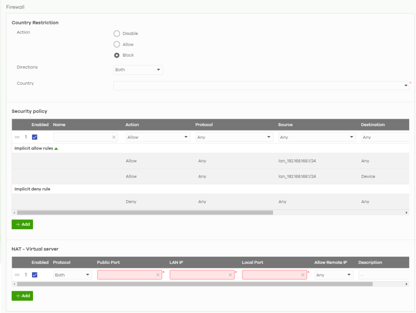
The following table describes the labels in this screen.
Label | Description |
|---|---|
Country Restriction | |
Action | Choose one of the following actions: • Disable: Select this to hide the Country Restriction settings. • Allow: Select this to allow packets from the selected countries IP address in the Country field. Dropping of packets from countries not in the Allow list will occur. • Block: Select this to drop packets from the selected countries IP address in the Country field. |
Directions | Select Both to allow incoming/outgoing packets to apply the firewall rules. Select Incoming to apply the firewall rules on incoming packets. Select Outgoing to apply the firewall rules on outgoing packets. |
Country | Select up to 10 countries or regions to apply the firewall rules configured in this screen. |
Security policy | |
 | Click the icon of a rule and drag the rule up or down to change the order. |
Enabled | Select the checkbox to turn on the rule. Otherwise, clear the checkbox to turn off the rule. |
Name | Enter the name of the security policy. |
Action | Select what the Nebula Device is to do with packets that match this rule. Select Deny to silently discard the packets without sending a TCP reset packet or an ICMP destination-unreachable message to the sender. Select Allow to permit the passage of the packets. |
Protocol | Select the IP protocol to which this rule applies. Choices are: ICMP, TCP, UDP, TCP and UDP and Any. |
Source | Specify the source IP addresses (LAN interface / country) to which this rule applies. You can add a CIDR, or enter a new IP address by clicking Customize IP. Enter Any to apply the rule to all IP addresses. |
Destination | Specify the destination IP addresses (LAN interface / country) or subnet to which this rule applies. You can add a CIDR, or enter a new IP address by clicking Customize IP. Enter Any to apply the rule to all IP addresses. |
Dst Port | Specify the destination ports to which this rule applies. By default, Any applies the rule to all ports. |
Description | Enter a descriptive name of up to 60 printable ASCII characters for the rule. |
 | Click this icon to remove the rule. |
Implicit allow rules | This shows the system generated Allow rules. • LAN interface / remote access VPN to Any • LAN interface / remote access VPN to Nebula Device |
Implicit deny rule | This shows the system generated Deny rule. • Any to Any |
Add | Click this button to create a new rule. |
NAT – Virtual server | |
 | Click the icon of a rule and drag the rule up or down to change the order. |
Enabled | Select the checkbox to turn on the rule. Otherwise, clear the checkbox to turn off the rule. |
Protocol | Select the IP protocol to which this rule applies. Choices are: TCP, UDP, and Both. |
Public Port | Enter the translated destination port or range of translated destination ports if this NAT rule forwards the packet. The remote user will try to connect to this port. |
LAN IP | Specify to which translated destination IP address this NAT rule forwards packets. This is the IP address of the internal server. |
Local Port | Enter the original destination port or range of destination ports this NAT rule supports. The internal server should respond to this port. |
Allow Remote IPs | Specify the remote IP addresses that are allowed to access the public IP address. You may restrict the remote users to connect from certain public IP addresses only. Select Any to allow all IP addresses. |
Description | Enter the descriptive name of the policy of up to 255 printable ASCII characters. |
 | Click this icon to remove the profile. |
Add | Click this button to create a new schedule profile. |
Site-to-Site VPN
A virtual private network (VPN) provides secure communications between sites without the expense of leased site-to-site lines. Use this screen to configure VPN rules.
Click Site-wide > Configure > Security router > Site-to-Site VPN to access this screen.
Site-wide > Configure > Security router > Site-to-Site VPN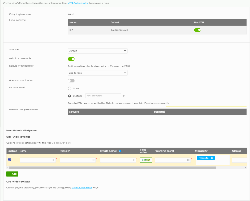
The following table describes the labels in this screen.
Label | Description |
|---|---|
Outgoing Interface | This displays WAN as the interface to which the VPN connection is going. |
Local network | This shows the local network behind the Nebula Device. |
Name | This shows the network name. |
Subnet | This shows the IP address and subnet mask of the computer on the network. |
Use VPN | Select ON to allow the computers on the network to use the VPN tunnel. Otherwise, select OFF. |
VPN Area | Select the VPN area of the site. For details, see VPN Areas. |
Nebula VPN enable | Click this to enable or disable site-to-site VPN on the site’s Nebula Device. If you disable this setting, the site will leave the VPN area. |
Nebula VPN Topology | Click this to select a topology for the VPN area. For details on topologies, see Topology Overview. Select disable to disable VPN connections for all sites in the VPN area. |
Area communication | Enable this to allow the site to communicate with sites in different VPN areas within the organization. |
NAT traversal | If the Nebula Device is behind a NAT router, select Custom to enter the public IP address or Auto or the domain name that is configured and mapped to the Nebula Device on the NAT router. In the NAT traversal pop-up, select WAN and Auto to allow NCC to detect automatically the public IP of your Nebula Device. |
Remote VPN participants | This shows all sites within the VPN area. |
Non-Nebula VPN peers | Configure this section to add a non-Nebula gateway to the VPN area. |
+ Add | Click this button to add a non-Nebula gateway to the VPN area. |
Enabled | Select the checkbox to enable VPN connections to the non-Nebula gateway. |
Name | Enter the name of the non-Nebula gateway/VPN. |
Public IP | Enter the public IPv4 address or FQDN of the non-Nebula gateway. |
Private subnet | Enter the IP subnet that will be used for VPN connections. This is the other side's LAN subnet, which you want to reach from your side. The IP range must be reachable from other devices in the VPN area. |
IPSec policy | Click to select a pre-defined policy or have a custom one. See IPsec Policy for detailed information. |
Preshared secret | Enter a pre-shared key (password). The Nebula Device and peer gateway use the key to identify each other when they negotiate the IKE SA. |
Availability | Select which sites the non-Nebula gateway can connect to in the VPN area. Select All sites to allow the non-Nebula gateway to connect to any site in the VPN area. Select This site and the non-Nebula gateway can only connect to the Nebula Device in this site. |
Address | Enter the address (physical location) of the device. |
 | Click this icon to remove the non-Nebula gateway. |
Add | Click this button to create a new non-Nebula gateway. |
IPsec Policy
Click the Default button in the Non-Nebula VPN peers section of the Site-wide > Configure > Security router > Site-to-Site VPN screen to access this screen.
Site-wide > Configure > Security router > Site-to-Site VPN: IPsec Policy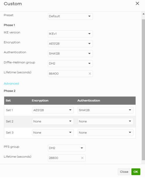
The following table describes the labels in this screen.
label | description |
|---|---|
Preset | Select a pre-defined IPSec policy, or select Custom to configure the policy settings yourself. |
Phase1 | IPSec VPN consists of two phases: Phase 1 (Authentication) and Phase 2 (Key Exchange). A phase 1 exchange establishes an IKE SA (Security Association). |
IKE version | Select IKEv1 or IKEv2. IKEv1 and IKEv2 applies to IPv4 traffic only. IKE (Internet Key Exchange) is a protocol used in setting up security associations that allows two parties to send data securely. |
Encryption | Select which key size and encryption algorithm to use in the IKE SA. Choices are: DES – a 56-bit key with the DES encryption algorithm 3DES – a 168-bit key with the DES encryption algorithm AES128 – a 128-bit key with the AES encryption algorithm AES192 – a 192-bit key with the AES encryption algorithm AES256 – a 256-bit key with the AES encryption algorithm The Nebula Device and the remote IPSec router must use the same key size and encryption algorithm. Longer keys require more processing power, resulting in increased latency and decreased throughput. |
Authentication | Select which hash algorithm to use to authenticate packet data in the IKE SA. Choices are SHA128, SHA256, SHA512 and MD5. SHA is generally considered stronger than MD5, but it is also slower. The remote IPSec router must use the same authentication algorithm. |
Diffie-Hellman group | Select which Diffie-Hellman key group (DHx) you want to use for encryption keys. Choices are: DH1 – use a 768-bit random number Modular Exponential (MODP) DH group DH2 – use a 1024-bit random number MODP DH5 – use a 1536-bit random number MODP DH14 – use a 2048-bit random number MODP DH19 – use a 256-bit random number elliptic curve group DH20 – use a 384-bit random number elliptic curve group DH21 – use a 521-bit random number elliptic curve group DH28 – use a 256-bit random number elliptic curve group DH29 – use a 384-bit random number elliptic curve group DH30 – use a 512-bit random number elliptic curve group Both routers must use the same DH key group. |
Lifetime (seconds) | Enter the maximum number of seconds the IKE SA can last. When this time has passed, the Nebula Device and remote IPSec router have to update the encryption and authentication keys and re-negotiate the IKE SA. This does not affect any existing IPSec SAs, however. |
Advanced | Click this to display a greater or lesser number of configuration fields. |
Mode | Set the negotiation mode. Main encrypts the Nebula Device’s and remote IPSec router’s identities but takes more time to establish the IKE SA. Aggressive is faster but does not encrypt the identities. |
Local ID | Enter an identifier used to identify the Nebula Device during authentication. This can be an IP address or hostname. |
Peer ID | Enter an identifier used to identify the remote IPSec router during authentication. This can be an IP address or hostname. |
Phase2 | Phase 2 uses the SA that was established in phase 1 to negotiate SAs for IPSec. |
Encryption | Select which key size and encryption algorithm to use in the IPSec SA. Choices are: (None) – no encryption key or algorithm DES – a 56-bit key with the DES encryption algorithm 3DES – a 168-bit key with the DES encryption algorithm AES128 – a 128-bit key with the AES encryption algorithm AES192 – a 192-bit key with the AES encryption algorithm AES256 – a 256-bit key with the AES encryption algorithm The Nebula Device and the remote IPSec router must both have at least one proposal that uses the same encryption and the same key. Longer keys are more secure, but require more processing power, resulting in increased latency and decreased throughput. |
PFS group | Select whether or not you want to enable Perfect Forward Secrecy (PFS) and, if you do, which Diffie-Hellman key group to use for encryption. Choices are: None – disable PFS DH1 – use a 768-bit random number Modular Exponential (MODP) DH group DH2 – use a 1024-bit random number MODP DH5 – use a 1536-bit random number MODP DH14 – use a 2048-bit random number MODP DH19 – use a 256-bit random number elliptic curve group DH20 – use a 384-bit random number elliptic curve group DH21 – use a 521-bit random number elliptic curve group DH28 – use a 256-bit random number elliptic curve group DH29 – use a 384-bit random number elliptic curve group DH30 – use a 512-bit random number elliptic curve group PFS changes the root key that is used to generate encryption keys for each IPSec SA. Both routers must use the same DH key group. PFS is ignored in initial IKEv2 authentication but is used when re-authenticating. |
Lifetime (seconds) | Enter the maximum number of seconds the IPSec SA can last. Shorter life times provide better security. The Nebula Device automatically negotiates a new IPSec SA before the current one expires, if there are users who are accessing remote resources. |
Close | Click this button to exit this screen without saving. |
OK | Click this button to save your changes and close the screen. |
Remote Access VPN
Use this screen to configure the VPN client settings on the Nebula Device. This allows incoming VPN clients to connect to the Nebula Device in order to access the site’s network. The clients have dynamic IP addresses and are also known as dial-in users. Only the clients can initiate the VPN tunnel.
Click Site-wide > Configure > Security router > Remote access VPN to access this screen.
Site-wide > Configure > Security router > Remote access VPN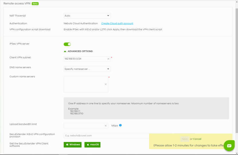
The following table describes the labels in this screen.
Label | Description |
|---|---|
NAT Traversal | If the Nebula Device is behind a NAT router, select + Customize IP to enter the public IP address that is configured and mapped to the Nebula Device on the NAT router. Select None to map to the WAN IP of the Nebula Device. NCC automatically updates the DNS server when the WAN IP changes. Or, select Auto to allow NCC to detect automatically the public IP of your Nebula Device. NCC automatically selects another WAN interface when the selected WAN interface is down. NCC automatically updates the DNS server when the public IP changes. |
Authentication | Select how the Nebula Device authenticates a remote user before allowing access to the VPN tunnel. Click Create a cloud auth account to create a Nebula Cloud Authentication Server user account. This will automatically add the site where you create remote access VPN setup to the Organization-wide > Organization-wide manage > Cloud authentication > User screen and bypass two-factor authentication. |
VPN configuration script download | Click the Windows, iOS/macOS or Android (strongSwan) icon to download a ZIP file containing the VPN remote access configuration script. After unzipping, save the certificate (.crt) and script (.bat) files to the same folder in your computer. This field is available only when the Nebula Device is online. |
IPSec VPN server | Select this to enable the IPsec VPN server. |
Client VPN subnet | Specify the IP addresses that the Nebula Device uses to assign to the VPN clients. The default subnet is 192.168.50.0/24. |
DNS name servers | Specify the DNS servers to assign to the remote users. Or select Specify nameserver to enter a static IP address. |
Custom name servers | If you select Specify nameserver in the DNS name servers field, manually enter the DNS server IP addresses. |
Upload Bandwidth Limit | Enter the maximum traffic load between VPN clients, 1 – 100 Mbps. |
SecuExtender IKEv2 VPN configuration provision | Enter the email address to send new IKEv2 Remote Access VPN configuration file to VPN client. Then click Send Email. The VPN client needs to replace the IPSec VPN client configuration by importing the configuration file. |
Get the SecuExtender VPN Client software | Click the Windows or macOS icon to download the SecuExtender VPN client software. |
SSID Settings
This screen allows you to configure up to 8 different SSID profiles for your Nebula Devices. An SSID, or Service Set IDentifier, is basically the name of the WiFi network to which a WiFi client can connect. The SSID appears as readable text to any device capable of scanning for WiFi frequencies (such as the WiFi adapter in a laptop), and is displayed as the WiFi network name when a person makes a connection to it.
Click Site-wide > Configure > Security router > SSID settings to access this screen.
Site-wide > Configure > Security router > SSID settings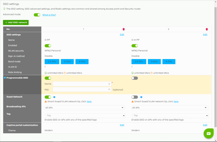
The following table describes the labels in this screen.
Label | Description |
|---|---|
Advanced mode | Select Off to disable Advanced mode. This allows you to create SSID profiles by only specifying an SSID name and optional password. NCC sets all other WiFi settings to default. |
+ Add SSID network | Click this button to configure up to 8 different SSID profiles for your Nebula Device. To configure more than 8 SSID profiles (up to 24), enable AP grouping in Site-wide > Configure > Access points > AP & port settings. For details, see AP & Port Settings. |
No. | This shows the index number of this profile. |
delete | Click this icon to remove the SSID profile. |
SSID settings | |
Edit | Click this button to go to the SSID advanced settings screen and configure WiFi security and advanced settings, such as band selection, enable assisted roaming and U-APSD (Unscheduled automatic power save delivery). See Site-wide > Configure > Access points > SSID advanced settings for more information on assisted roaming and U-APSD. |
Name | This shows the SSID name for this profile. Click the text box and enter a new SSID if you want to change it. |
Enabled | Click to turn on or off this profile. |
WLAN security | This shows the encryption method used in this profile. |
Sign-in method | This shows the authentication method used in this profile or Disable. |
Band mode | This shows whether the SSID use either 2.4 GHz band, 5 GHz band, or the 6 GHz band. |
VLAN ID | This shows the ID number of the VLAN to which the SSID belongs. |
Rate limiting | This shows the maximum incoming/outgoing transmission data rate (in Kbps) on a per-station basis. |
Programmable SSID | Select On to have each Nebula Device that uses this SSID generate a unique SSID name and pre-shared key (PSK) based on the Nebula Device’s model name, serial number, or MAC address. For example, a hotel can install a Nebula Device in each room and then have each Nebula Device broadcast a unique SSID based on the room number: FreeWiFi_Room1, FreeWiFi_Room2, FreeWiFi_Room3, and so on. |
Name | Name: Enter a programmable SSID name in the format PREFIX+VALUE(X). This name overrides the original SSID name. • PREFIX: Optional prefix to add to the SSID, for example “FreeWiFi_”. To use “$” in the SSID name, enter “$$” • VALUE: Specify a Nebula Device value to use to generate the SSID name. Use one of the following: $AP = Nebula Device device name. $MAC = Nebula Device MAC address. $SN = Nebula Device serial number. • X: Specify how many characters of the Nebula Device value to use in the SSID. A positive number means the first X characters, and a negative number means the last X characters. Example: FreeWiFi_Room$AP(–3) generates an SSID called “FreeWiFi_Room” + the last three characters of the access point device name. |
PSK | PSK: Enter an optional programmable PSK in the format GENTYPE(Y). • GENTYPE: Specify how the Nebula Device will generate a random PSK. $GENMIX = The Nebula Device generates a mix of random letters and numbers. $GENNUM = The Nebula Device generates a mix of random numbers only. $AP = Nebula Device device name. $MAC = Nebula Device MAC address. $SN = Nebula Device serial number. Y = Specify the length of the PSD. The minimum length is 8. Example 1: $GENNUM(10) generates a unique 10-character PSK for this SSID, consisting only of numbers. Example 2: $MAC(-5)$SN(-5) uses the MAC address’s last 5 characters and the serial number’s last 5 characters (for example, 8E3AE02451). Example 3: ZYXEL-$GENMIX(4) appends the fixed characters ‘ZYXEL’ and generates a unique 4-character mix of random letters and numbers (for example, ZYXEL-3c4d). |
Guest Network | Select On to set this WiFi network as a guest network. Layer 2 isolation and intra-BSS blocking are automatically enabled on the SSID. WiFi clients connecting to this SSID can access the Internet through the Nebula Device but cannot directly connect to the LAN or the WiFi clients in the same SSID or any other SSIDs. 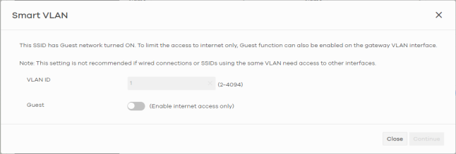 |
Broadcasting APs | Select All APs or specify the AP to use this SSID profile. |
Tag | Enter or select the tags you created for Nebula Devices in the Site-wide > Devices > Access points screen or Site-wide > Devices > Access points: Details screen. Only the Nebula Devices with the specified tag will broadcast this SSID. If you leave this field blank, all the Nebula Devices on the site will broadcast this SSID. |
Captive portal customization | |
Edit | Click this button to go to the Captive portal screen and configure the captive portal settings. See Captive Portal Customization. |
Theme | If captive portal is enabled, this shows the name of the captive portal page used in this profile. |
SSID Advanced Settings
Use this screen to configure WiFi security, band selection, assisted roaming and U-APSD (Unscheduled automatic power save delivery) settings for the SSID profiles.
Click Site-wide > Configure > Security router > SSID advanced settings to access this screen.
Site-wide > Configure > Security router > SSID advanced settings Part 1
Site-wide > Configure > Security router > SSID advanced settings Part 2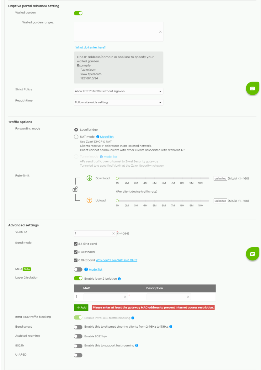
The following table describes the labels in this screen.
Label | Description |
|---|---|
SSID advanced settings | Select the SSID profile to which the settings you configure here is applied. |
Basic information | |
SSID name | This shows the SSID name as it appears to WiFi clients. Click the text box and enter a new SSID if you want to change it. |
Enabled | Click this to enable the SSID to be discoverable by WiFi clients. |
Hide SSID | Click this if you want to hide your SSID from WiFi clients. This tells any WiFi clients in the vicinity of the Nebula Device using this SSID profile not to display its SSID name as a potential connection. When an SSID is “hidden” and a WiFi client cannot see it, the only way you can connect to the SSID is by manually entering the SSID name in your WiFi connection setup screens. |
Network access | |
Security options | Select Open to allow any client to associate this network without any data encryption or authentication. Select Enhanced-open to allow any client to associate this network without any password but with improved data encryption. Upon selecting Enhanced-open or WPA Personal With WPA3, transition mode generates two VAP so devices that do not support Enhanced-Open/WPA Personal With WPA3 can connect using Open/WPA Personal With WPA2 network. This is always on at the time of writing. Select WPA Personal With (WPA2/WPA3) and enter a pre-shared key from 8 to 63 case-sensitive keyboard characters to enable WPA2/3-PSK data encryption. Upon selecting WPA Personal With WPA3, Nebula Devices that do not support it will revert to WPA2. • Turn on 802.11r to enable IEEE 802.11r fast roaming on the access point. 802.11r fast roaming reduces the delay when the clients switch from one Nebula Device to another by allowing security keys to be stored on all Nebula Devices in a network. Information from the original association is passed to the new Nebula Device when the client roams. The client does not need to perform the whole 802.1x authentication process. Click Print to display the QR code that includes the password for quick access. You can save the QR code as PDF. To test, use a smartphone to scan the QR code. Click to join the network. The client device should connect to WiFi directly without asking the password. Select Dynamic personal psk to have every user connect to the SSID using a unique pre-shared key (PSK) that is linked to their user account. This allows you to revoke a user’s WiFi network access by disabling their account. After enabling this option, you must create one or more DPPSK users in the site or organization at Site-wide > Configure > Cloud authentication > Account Type > DPPSK. • For details on creating a site DPPSK user, see Cloud Authentication DPPSK Screen. • For details on creating organization DPPSK users, see Create/Update User Account. Turn on MAC-based Authentication with to authenticate WiFi clients by their MAC addresses together with My RADIUS server to use an external RADIUS server. Or select Nebula cloud authentication to use the NCC for MAC authentication. Select WPA-Enterprise with to enable 802.1X secure authentication. You can select My RADIUS server to use an external RADIUS server or select Nebula cloud authentication to use the NCC for 802.1X authentication. • Turn on 802.11r to enable IEEE 802.11r fast roaming on the Nebula Device. 802.11r fast roaming reduces the delay when the clients switch from one Nebula Device to another by allowing security keys to be stored on all Nebula Devices in a network. Information from the original association is passed to the new Nebula Device when the client roams. The client does not need to perform the whole 802.1x authentication process. • Select Two-Factor Authentication to require that the user log in using both their password and a Google Authenticator code. To log in, users must have Two-Factor Authentication enabled on their account and have setup Google Authenticator on their mobile device. Select Enable on RAP only to only require Two-Factor Authentication when accessing the network through a remote access point (RAP). |
Rate-limit | Set the maximum data download and upload rates in Kbps, on a per-station basis. Click a lock icon to change the lock state. If the lock icon is locked, the limit you set applies to both download and upload traffic. If the lock is unlocked, you can set download and upload traffic to have different transmission speeds. |
Advanced settings | |
VLAN ID | This shows the ID number of the VLAN to which the SSID belongs. |
Band mode | Select to have the SSID use either 2.4 GHz band, 5 GHz band, or 6 GHz band only. |
Layer 2 isolation | This field is not configurable if you select NAT mode. Select to turn on or off layer-2 isolation. If a device’s MAC addresses is NOT listed, it is blocked from communicating with other devices in an SSID on which layer-2 isolation is enabled. Click Add to enter the MAC address of each device that you want to allow to be accessed by other devices in the SSID on which layer-2 isolation is enabled. |
Intra-BSS traffic blocking | Click this switch to the left to prevent crossover traffic from within the same SSID. Click this switch to the right to allow intra-BSS traffic. |
Band select | Select to enable band steering. When enabled, the Nebula Device steers WiFi clients to the 5 GHz band. |
Assisted roaming | Select to turn on or off IEEE 802.11k/v assisted roaming on the Nebula Device. When the connected clients request 802.11k neighbor lists, the Nebula Device will response with a list of neighbor Nebula Devices that can be candidates for roaming. When the 802.11v capable clients are using the 2.4 GHz band, the Nebula Device can send 802.11v messages to steer clients to the 5 GHz band. |
802.11r | Select to turn on or off IEEE 802.11r fast roaming on the Nebula Device. 802.11r fast roaming reduces the delay when the clients switch from one Nebula Device to another, by allowing security keys to be stored on all Nebula Devices in a network. Information from the original association is passed to the new Nebula Device when the client roams. The client does not need to perform the whole 802.1x authentication process. |
U-APSD | Select to turn on or off Automatic Power Save Delivery. This helps increase battery life for battery-powered WiFi clients connected to the Nebula Device. |
SSID schedule | |
Enabled | Click this switch to the right to enable and configure a schedule. |
Schedule | Select a schedule to control when the SSID is enabled or disabled. You can click the edit icon to change the schedule name. |
Schedule templates | Select a pre-defined schedule template or select Custom schedule and manually configure the day and time at which the SSID is enabled or disabled. |
Day | This shows the day of the week. |
Availability | Click this switch to the right to enable the SSID at the specified time on this day. Otherwise, click this switch to the left to disable the SSID on the day and at the specified time. Specify the hour and minute when the schedule begins and ends each day. |
Add | Click this button to create a new schedule. A window pops up asking you to enter a descriptive name for the schedule for identification purposes. 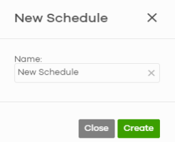 |
Delete | Click this button to remove a schedule which is not used in any SSID profile. |
Radio Settings
Use this screen to configure global radio settings for the Nebula Device in the site. Click Site-wide > Configure > Security router > Radio settings to access this screen.
Site-wide > Configure > Security router > Radio settings Part 1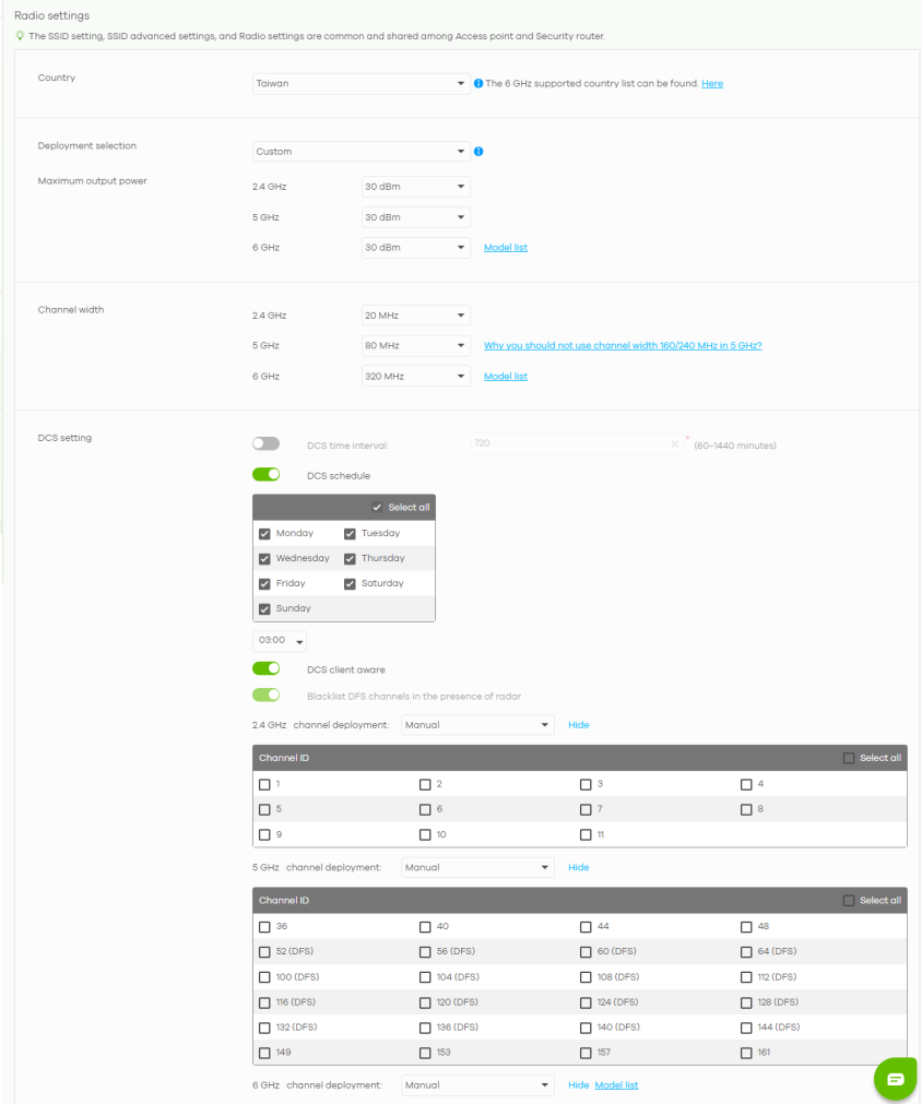
Site-wide > Configure > Security router > Radio settings Part 2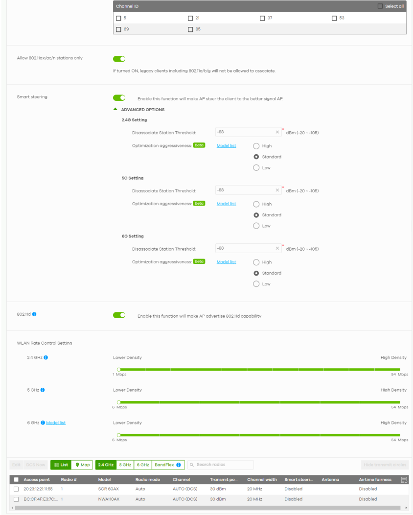
The following table describes the labels in this screen.
Label | Description |
|---|---|
Country | Select the country where the Nebula Device is located or installed. The available channels vary depending on the country you selected. Be sure to select the correct or same country for both radios on a Nebula Device and all connected Nebula Devices in order to prevent roaming failure and interference with other systems. |
Deployment selection | Select High-density (More than 10 APs) for the lowest output power for 10 or more Access Points. Select Moderate-density (6-9 APs) for moderate output power for 5 to 9 Access Points. Select Low-density (2-5 APs) for higher concentration of output power for less than 5 Access Points. Select Single AP for highest concentration of output power for a single Access Point. |
Maximum output power | Selecting any of the options in the Deployment selection field will automatically set the maximum output power for 2.4 / 5 / 6 GHz. But you can change the setting (1 – 30 dBm). |
Channel width | Select the wireless channel bandwidth you want the Nebula Device to use. A standard 20 MHz channel offers transfer speeds of up to 144 Mbps (2.4 GHz) or 217 Mbps (5 GHz) whereas a 40 MHz channel uses two standard channels and offers speeds of up to 300 Mbps (2.4 GHz) or 450 Mbps (5 GHz). An IEEE 802.11ac-specific 80 MHz channel offers speeds of up to 1.3 Gbps. 40 MHz (channel bonding or dual channel) bonds two adjacent radio channels to increase throughput. An 80 MHz channel consists of two adjacent 40 MHz channels. The WiFi clients must also support 40 MHz or 80 MHz. It is often better to use the 20 MHz setting in a location where the environment hinders the WiFi signal. |
DCS setting | |
DCS time interval | Select ON to set the DCS time interval (in minutes) to regulate how often the Nebula Device surveys the other Nebula Devices within its broadcast radius. If the channel on which it is currently broadcasting suddenly comes into use by another Nebula Device, the Nebula Device will then dynamically select the next available clean channel or a channel with lower interference. |
DCS schedule | Select ON to have the Nebula Device automatically find a less-used channel within its broadcast radius at a specific time on selected days of the week. You then need to select each day of the week and specify the time of the day (in 24-hour format) to have the Nebula Device use DCS to automatically scan and find a less-used channel. |
DCS client aware | Select ON to have the Nebula Device wait until all connected clients have disconnected before switching channels. |
Avoid 5G DFS channel | If your Nebula Devices are operating in an area known to have RADAR devices, the Nebula Device will choose non-DFS channels to provide a stable WiFi service. |
Blacklist DFS channels in the presence of radar | Select ON to blacklist a channel if RADAR is detected. After being blacklisted, the Nebula Device will not use the channel again until the Nebula Device is rebooted. However, the Nebula Device can still use other DFS channels. |
2.4 GHz channel deployment | Select All available channels to allow channel-hopping to have the Nebula Device automatically select the best channel. Select Manual to select the individual channels the Nebula Device switches between. |
5 GHz channel deployment | Select how you want to specify the channels the Nebula Device switches between for 5 GHz operation. Select All available channels to have the Nebula Device automatically select the best channel. Select Manual to select the individual channels the Nebula Device switches between. |
6 GHz channel deployment | Select how you want to specify the channels the Nebula Device switches between for 6 GHz operation. Select All available channels to have the Nebula Device automatically select the best channel. Select Manual to select the individual channels the Nebula Device switches between. |
Allow 802.11ax/ac/n stations only | Select ON to have the Nebula Device allow only IEEE 802.11n/ac/ax clients to connect, and reject IEEE 802.11a/b/g clients. |
Smart Steering | Select ON to enable smart client steering on the Nebula Device. Client steering helps monitor WiFi clients and drop their connections to optimize the bandwidth when the clients are idle or have a low signal. When a WiFi client is dropped they have the opportunity to steer to a Nebula Device with a strong signal. Additionally, dual band WiFi clients can also steer from one band to another. Select OFF to disable this feature on the Nebula Device. |
ADVANCED OPTIONS | Click this to display a greater or lesser number of configuration fields. |
2.4G/5G/6G Setting | |
Disassociate Station Threshold | Set a minimum kick-off signal strength. When a WiFi client’s signal strength is lower than the specified threshold, the Nebula Device disconnects the WiFi client. –20 dBm is the strongest signal you can require and –105 dBm is the weakest. |
Optimization aggressiveness | High, Standard and Low stand for different traffic rate threshold levels. The level you select here decides when the Nebula Device takes action to improve the Access Point’s WiFi network performance. The Nebula Device will postpone the actions implemented on Access Points until your network is less busy if the threshold is exceeded. Select a suitable traffic rate threshold level for your network. High: Select this if you want the Nebula Device to postpone the action set when the Access Point network traffic is heavy. Standard: Select this if you want the Nebula Device to postpone the action set when the Access Point network traffic is medium. Low: Select this if you want the Nebula Device to postpone the action set when the Access Point network traffic is low. |
802.11d | Click this to enable 802.11d on the Access Point. 802.11d is a WiFi network specification, for use in countries where 802.11 WiFi is restricted. Enabling 802.11d causes the Nebula Device to broadcast the country where it is located, which is determined by the Country setting. |
WLAN Rate Control Setting | |
2.4 GHz / 5 GHz / 6 GHz | Sets the minimum data rate that 2.4 GHz, 5 GHz, and 6 GHz WiFi clients can connect to the Nebula Device, in Mbps. Increasing the minimum data rate can reduce network overhead and improve WiFi network performance in high density environments. However, WiFi clients that do not support the minimum data rate will not be able to connect to the Nebula Device. |
Edit | Click this button to modify the channel, output power, channel width, airtime fairness (the same setting will apply to both 2.4 GHz and 5 GHz), and smart steering settings for the selected Nebula Devices. On the Nebula Device that comes with internal antennas and also has an antenna switch, you can adjust coverage depending on the orientation of the antenna for the Nebula Device radios. Select Wall if you mount the Nebula Device to a wall. Select Ceiling if the Nebula Device is mounted on a ceiling. You can switch from Wall to Ceiling if there are still WiFi dead zones, and so on. If you select Hardware Switch, you use the physical antenna switch to adjust coverage and apply the same antenna orientation settings to both radios. 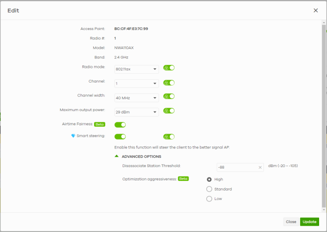 |
DCS Now | Click this button to have the selected Nebula Devices immediately scan for and select a channel that has least interference. |
List | Click this to display a list of all connected Nebula Devices. |
Map | Click this to display the locations of all connected Nebula Devices on the Google map. |
2.4 GHz | Click this to display the connected Nebula Devices using the 2.4 GHz frequency band. |
5 GHz | Click this to display the connected Nebula Devices using the 5 GHz frequency band. |
6 GHz | Click this to display the connected Nebula Devices using the 6 GHz frequency band. |
BandFlex | Click this to display the connected Nebula Devices that supports BandFlex (5 GHz or 6 GHz frequency bands). |
Hide transmit circles | Click this button to not show the transmission range on the Map. |
Access point | This displays the descriptive name or MAC address of the connected Nebula Device. |
Radio # | This displays the number of the connected Nebula Device’s radio. |
Model | This displays the model name of the connected Nebula Device. |
Radio mode | This displays the type of WiFi radio the Nebula Device is currently using, for example 802.11b/g/n. |
Channel | This displays the channel ID currently being used by the connected Nebula Device’s radio. |
Transmit power | This displays the current transmitting power of the connected Nebula Device’s radio. If the Nebula Device is offline, this shows the maximum output power you configured for the Nebula Device. |
Channel width | This displays the wireless channel bandwidth the connected Nebula Device’s radio is set to use. |
Smart steering | This displays whether smart client steering is enabled or disabled on the connected Nebula Devices. |
Antenna | This displays the antenna orientation settings for the Nebula Device that comes with internal antennas and also has an antenna switch. |
Airtime fairness | This displays whether airtime fairness is enabled or disabled on the connected Nebula Device. |
 | Click this icon to display a greater or lesser number of configuration fields. For faster loading of data, select only the configuration fields listed that do NOT take a long time to fetch data. |
Router Settings
Use this screen to configure DNS settings.
Click Site-wide > Configure > Security router > Router settings to access this screen.
Site-wide > Configure > Security router > Router settings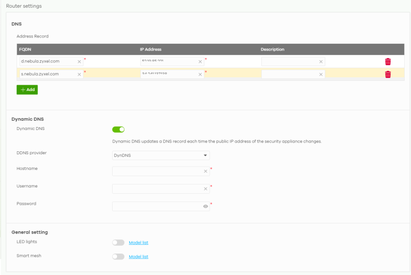
The following table describes the labels in this screen.
Label | Description |
|---|---|
DNS | |
Address Record | This record specifies the mapping of a Fully-Qualified Domain Name (FQDN) to an IP address. An FQDN consists of a host and domain name. For example, www.zyxel.com.tw is a fully qualified domain name, where “www” is the host, “zyxel” is the third-level domain, “com” is the second-level domain, and “tw” is the top level domain. |
FQDN | Enter a host’s fully qualified domain name. Use up to 247 characters, a-ZA-Z0-9.–. Use "*." as a prefix in the FQDN for a wildcard domain name (for example, *.example.com). |
IP Address | Enter the host’s IP address. |
Description | Enter the descriptive name of the DNS record of up to 255 printable ASCII characters. |
 | Click this icon to remove the entry. |
Add | Click this button to create a new entry, maximum up to 20. |
Dynamic DNS | |
Dynamic DNS | Click On to use dynamic DNS. Otherwise, select Off to disable it. |
DDNS provider | Select your Dynamic DNS service provider from the drop-down list box. If you select User customize, create your own DDNS service. |
Hostname | Enter the domain name you registered. |
Username | Enter the user name (email format) used when you registered your domain name. Up to 253 characters, A-Za-z0-9@.–_. |
Password | Enter the password provided by the DDNS provider. Up to 53 characters, 0-9a-zA-Z~!@#$%^&*()_-+={[}]|\:;”’<,>.?/ |
Connection type | Select Http (Hypertext Transfer Protocol) to use the standard protocol for sending data between a browser and a website. HTTP transmits data in plain text, which means that third parties can intercept and read the information. Select Https (Hypertext Transfer Protocol Secure) to use HTTP with encryption and verification. This prevents third parties from eavesdropping on communications to and from the server. |
URL | Enter the URL that can be used to access the server that will host the DDNS service. |
General setting | |
LED lights | Click to turn on or off the LEDs on the Nebula Devices. Click Model list to see the supported Security router. |
Smart mesh | Click to enable or disable the Nebula Smart Mesh feature on all Nebula Devices in the site. Click Model list to see whether your Nebula Device supports Nebula Smart Mesh. |