Web Configurator
Overview
This section introduces the configuration and functions of the Web Configurator.
The Web Configurator is an HTML-based management interface that allows easy system setup and management through a web browser. Use a web browser that supports HTML5, such as Microsoft Edge, Mozilla Firefox, or Google Chrome. The recommended minimum screen resolution is 1024 by 768 pixels.
In order to use the Web Configurator you need to allow:
• Web browser pop-up windows on your computer.
• JavaScript (enabled by default).
• Java permissions (enabled by default).
System Login
1 Start your web browser.
2 The Switch is a DHCP client by default. Type “https://DHCP-assigned IP” in the Location or Address field. Press [ENTER].
If the Switch is not connected to a DHCP server, type “https://” and the static IP address of the Switch (for example, the default management IP address is 192.168.1.1 through an in-band port) in the Location or Address field. Press [ENTER]. Your computer must be in the same subnet in order to access this website address.
Also, you can use the ZON Utility to check your Switch’s IP address. See Zyxel One Network (ZON) Utility for more information on the ZON utility.
3 If a “Your connection is not private” screen appears, click Advanced and Proceed to DHCP-assigned IP (unsafe) to go to the Login screen. This screen appears as the Zyxel Device uses a certificate for the HTTPS connection. See Certificates for information on using an HTTPS certificate verified by a third party to create secure HTTPS connections between your computer and the Switch.
Unsafe Login Warning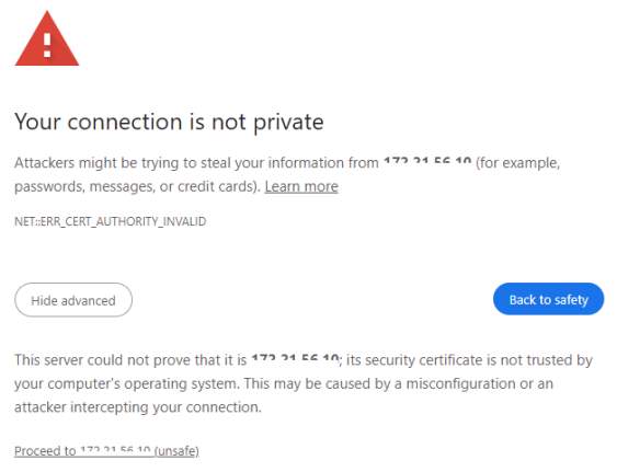
The Login screen appears.
Web Configurator: Login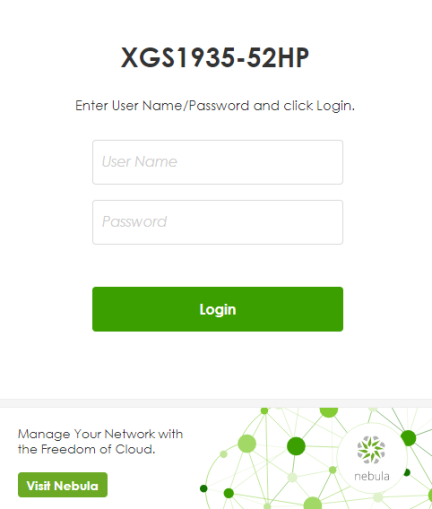
Web Configurator: Login (Cloud mode)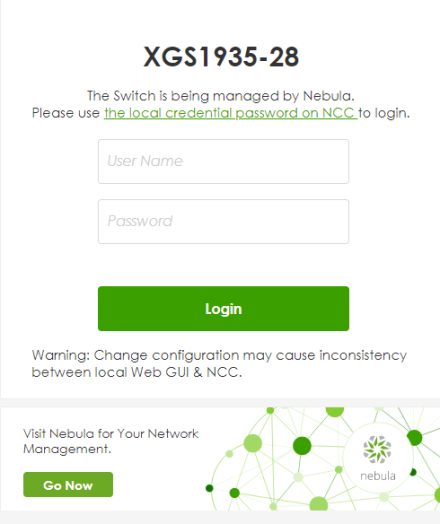
4 In Standalone mode, click the Visit Nebula button if you want to open the Zyxel Nebula Control Center (NCC) login page in a new tab or window. In Cloud mode, click the Go Now button. The NCC is a cloud-based network management system that allows you to remotely manage and monitor the Switch. See Mode Changing for information on changing your Switch to Nebula Cloud management.
Visit Nebula
5 Alternatively, click Login to log into the Web Configurator to manage the Switch directly.
In Standalone mode, the default user name is admin and associated default password is 1234.
In Cloud mode, use the Local credentials: password to login. The Local credentials: Password can be found in Site-wide > Configure > Site settings > Device configuration in the NCC portal. See the NCC User’s Guide for more information.
In Standalone mode, the change password screen appears the first time you log in using the default password.
Change Password Screen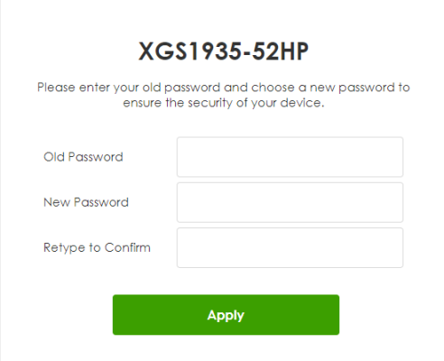
6 After setting the new password, close and restart your web browser. Enter the ‘https://DHCP-assigned IP’ in the URL field and press [ENTER]. When the login screen appears, enter the user name (default: ‘admin’) and new password.
Password Changed Screen 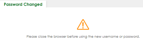
7 The Setup Wizard screen will appear. You can use the Setup Wizard screen to configure the Switch’s IP, login password, SNMP community, link aggregation, and view a summary of the settings. When you finish configuring the settings, you can click the Apply & Save button to make the settings take effect, and save your configuration into the Switch’s non-volatile memory at once. Check the screens to see if the settings are applied.
You can select the Ignore this wizard next time checkbox and click Apply & Save if you do not want the Setup Wizard screen to appear the next time you log in. If you want to open the Setup Wizard screen later, click the Wizard icon in the upper right hand corner of the Web Configurator.
Web Configurator: Wizard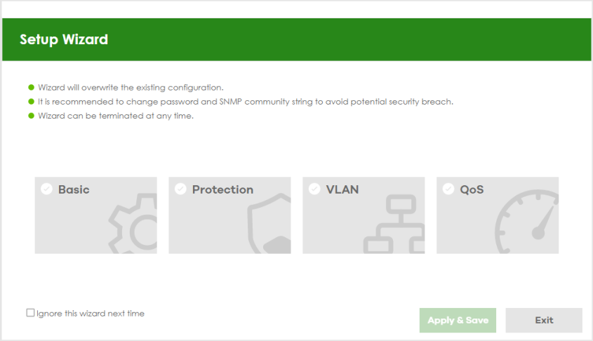
8 If you did not change the default SNMP community values and enabled SNMP in SECURITY > Access Control > Service Access Control, a warning screen displays each time you log into the Web Configurator. Click SNMP to open a screen where you can change the SNMP community string, see Configure SNMP for more information. Otherwise, click Ignore to close it.
SNMP Setting
Web Configurator: Warning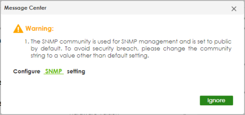
SYSTEM > SNMP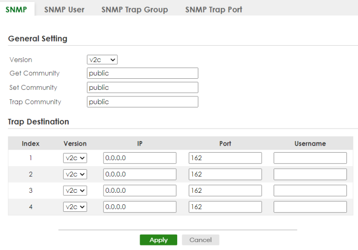
Zyxel One Network (ZON) Utility
ZON Utility is a program designed to help you deploy and manage a network more efficiently. It detects devices automatically and allows you to do basic settings on devices in the network without having to be near it.
The ZON Utility issues requests through Zyxel Discovery Protocol (ZDP) and in response to the query, the device responds back with basic information including IP address, firmware version, location, system and model name in the same broadcast domain. The information is then displayed in the ZON Utility screen and you can perform tasks like basic configuration of the devices and batch firmware upgrade in it. You can download the ZON Utility at https://www.zyxel.com/global/en/form/zon-utility-download and unzip it first before installing it in a computer (Windows operating system).
Requirements
Before installing the ZON Utility in your computer, please make sure it meets the requirements listed below.
Operating System
At the time of writing, the ZON Utility is compatible with:
• Windows 7 (both 32-bit / 64-bit versions)
• Windows 8 (both 32-bit / 64-bit versions)
• Windows 8.1 (both 32-bit / 64-bit versions)
• Windows 10 (both 32-bit / 64-bit versions)
• Windows 11 (64-bit version)
Hardware
Here are the minimum hardware requirements to use the ZON Utility on your computer.
• Core i3 processor
• 2 GB RAM
• 100 MB free hard disk
• WXGA (Wide XGA 1280 by 800)
Run the ZON Utility
1 Double-click the ZON Utility to run it.
2 Select a network adapter to which your supported devices are connected.
Network Adapter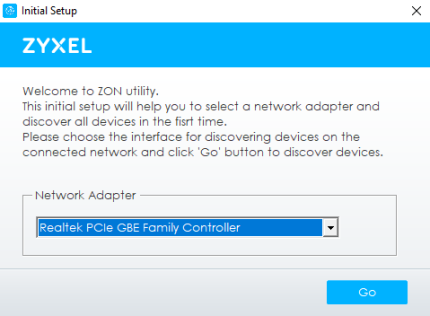
3 Click the Go button for the ZON Utility to discover all supported devices in your network.
Discovery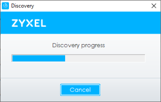
4 The ZON Utility screen shows the devices discovered.
ZON Utility Screen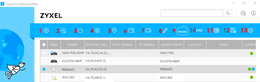
5 Select a device and then use the icons to perform actions. Some functions may not be available for your devices.
Password Prompt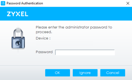
The following table describes the icons numbered from left to right in the ZON Utility screen.
icon | DESCRIPTION |
|---|---|
1 IP Configuration | Change the selected device’s IP address. |
2 Renew IP Address | Update a DHCP-assigned dynamic IP address. |
3 Reboot Device | Use this icon to restart the selected devices. This may be useful when troubleshooting or upgrading new firmware. |
4 Reset Configuration to Default | Use this icon to reload the factory-default configuration file. This means that you will lose all previous configurations. |
5 Locator LED | Use this icon to locate the selected device by causing its Locator LED to blink. |
6 Web GUI | Use this to access the selected device Web Configurator from your browser. You will need a user name and password to log in. |
7 Firmware Upgrade | Use this icon to upgrade new firmware to selected devices of the same model. Make sure you have downloaded the firmware from the Zyxel website to your computer and unzipped it in advance. |
8 Change Password | Use this icon to change the admin password of the selected device. You must know the current admin password before changing to a new one. |
9 Configure NCC Discovery | You must have Internet access to use this feature. Use this icon to enable or disable the Nebula Control Center (NCC) discovery feature on the selected device. If it is enabled, the selected device will try to connect to the NCC. Once the selected device is connected to and has registered in the NCC, it will go into the Nebula cloud management mode. |
10 ZAC | Use this icon to run the Zyxel AP Configurator of the selected AP. |
11 Clear and Rescan | Use this icon to clear the list and discover all devices on the connected network again. |
12 Save Configuration | Use this icon to save configuration changes to permanent memory on a selected device. |
13 Settings | Use this icon to select a network adapter for the computer on which the ZON utility is installed, and the utility language. |
The following table describes the fields in the ZON Utility main screen.
label | description |
|---|---|
Type | This field displays an icon of the kind of device discovered. |
Model | This field displays the model name of the discovered device. |
Firmware Version | This field displays the firmware version of the discovered device. |
MAC Address | This field displays the MAC address of the discovered device. |
IP Address | This field displays the IP address of an internal interface on the discovered device that first received a ZDP discovery request from the ZON Utility. |
System Name | This field displays the system name of the discovered device. |
Location | This field displays where the discovered device is. |
Status | This field displays whether changes to the discovered device have been done successfully. As the Switch does not support IP Configuration, Renew IP address and Flash Locator LED, this field displays “Update failed”, “Not support Renew IP address” and “Not support Flash Locator LED” respectively. |
Controller Discovery | This field displays if the discovered device supports the Nebula Control Center (NCC) discovery feature. If it is enabled, the selected device will try to connect to the NCC. Once the selected device is connected to and has registered in the NCC, it will go into the Nebula cloud management mode. |
Serial Number | Enter the admin password of the discovered device to display its serial number. |
Hardware Version | This field displays the hardware version of the discovered device. |
IPv6 Address | This field displays the IPv6 address on the discovered device that first received a ZDP discovery request from the ZON Utility. |
If you want to check the supported models and firmware versions, you can click the Show information about ZON icon in the upper right of the screen. Then select the Supported model and firmware version link. If your device is not listed here, see the device release notes for ZON Utility support. The release notes are in the firmware zip file on the Zyxel web site.
ZON Utility Screen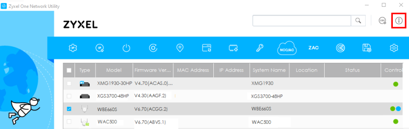
Wizard
The Setup Wizard contains the following parts:
• Basic – to configure the Switch IP address, DNS server, system password, SNMP community and link aggregation (trunking).
• Protection – to enable loop guard and broadcast storm control on the Switch and its ports.
• VLAN – to create a static VLAN, assign ports to the VLAN and set the ports to tag or untag outgoing frames.
• QoS – to determine a port’s IEEE 802.1p priority level for QoS.
Setup Wizard
Basic
In Basic, you can set up IP/DNS, set up your password, SNMP community, link aggregation, and view finished results.
In order to set up your IP/DNS, please do the following. Click Wizard > Basic > Step 1 IP to access this screen.
Wizard > Basic > Step 1 IP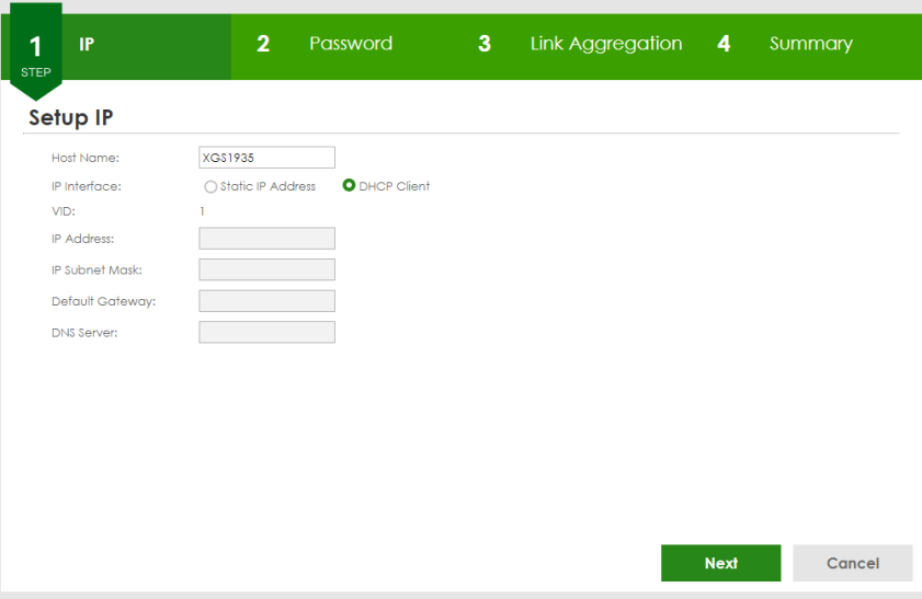
Each field is described in the following table.
Label | Description |
|---|---|
Host Name | This field displays a host name. Enter a string to set a new host name. The host name should not contain [ ? ], [ | ], [ ' ], [ " ], or [ , ]. |
IP Interface | Select DHCP Client if the Switch is connected to a router with the DHCP server enabled. You then need to check the router for the IP address assigned to the Switch in order to access the Switch’s Web Configurator again. Select Static IP Address when the Switch is NOT connected to a router or you want to assign it a fixed IP address. |
VID | This field displays the VLAN ID. |
IP Address | The Switch needs an IP address for it to be managed over the network. |
IP Subnet Mask | The subnet mask specifies the network number portion of an IP address. |
Default Gateway | Type the IP address of the default outgoing gateway in dotted decimal notation, for example 192.168.1.254. |
DNS Server | DNS (Domain Name System) is for mapping a domain name to its corresponding IP address and so forth. Enter a domain name server IP address in order to be able to use a domain name instead of an IP address. |
Next | Click Next to show the next screen. |
Cancel | Click Cancel to exit this screen without saving. |
After clicking Next, the Password screen appears.
Wizard > Basic > Step 2 Password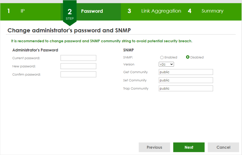
In the Password fields, [ space ] is also not allowed.
Each field is described in the following table.
Label | Description |
|---|---|
Administrator's Password | |
Current password | Type the existing system password (1234 is the default password when shipped). |
New password | Enter your new system password. Up to 32 printable ASCII characters are allowed for the new password. |
Confirm password | Retype your new system password for confirmation. |
SNMP | |
SNMP | Select Enabled to let the Switch act as an SNMP agent, which allows a manager station to manage and monitor the Switch through the network. Select Disabled to turn this feature off. |
Version | Select the SNMP version for the Switch. The SNMP version on the Switch must match the version on the SNMP manager. Choose SNMP version 2c (v2c), SNMP version 3 (v3) or both (v3v2c). |
Get Community | Enter the Get Community string, which is the password for the incoming Get- and GetNextrequests from the management station. The Get Community string is only used by SNMP managers using SNMP version 2c or lower. |
Set Community | Enter the Set Community string, which is the password for the incoming Set- requests from the management station. The Set Community string is only used by SNMP managers using SNMP version 2c or lower. |
Trap Community | Enter the Trap Community string, which is the password sent with each trap to the SNMP manager. The Trap Community string is only used by SNMP managers using SNMP version 2c or lower. |
Previous | Click Previous to show the previous screen. |
Next | Click Next to show the next screen. |
Cancel | Click Cancel to exit this screen without saving. |
After clicking Next, the Link Aggregation screen appears.
Wizard > Basic > Step 3 Link Aggregation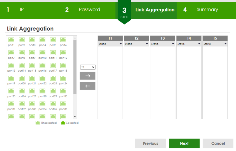
Each field is described in the following table.
Label | Description |
|---|---|
Link Aggregation | |
T1-Tx | Click the arrows to add or delete icons located on the left to desired preference. Select Static if the ports are configured as static members of a trunk group. Select LACP if the ports are configured to join a trunk group through LACP. |
Previous | Click Previous to show the previous screen. |
Next | Click Next to show the next screen. |
Cancel | Click Cancel to exit this screen without saving. |
After clicking Next, the Summary screen appears.
Wizard > Basic > Step 4 Summary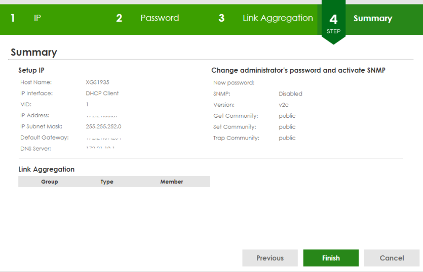
Each field is described in the following table.
Label | Description |
|---|---|
Setup IP | |
Host Name | This field displays a host name. |
IP Interface | This field displays whether the WAN interface is using a DHCP IP address or a static IP address. |
VID | This field displays the VLAN ID. |
IP Address | The Switch needs an IP address for it to be managed over the network. |
IP Subnet Mask | The subnet mask specifies the network number portion of an IP address. |
Default Gateway | Type the IP address of the default outgoing gateway in dotted decimal notation, for example 192.168.1.254. |
DNS Server | DNS (Domain Name System) is for mapping a domain name to its corresponding IP address and vice versa. Enter a domain name server IP address in order to be able to use a domain name instead of an IP address. |
Change administrator's password and activate SNMP | |
New Password | This field displays asterisks when a new password has been created. |
SNMP | This field displays whether the Switch acts as an SNMP agent. |
Version | This field displays the SNMP version for the Switch. |
Get Community | This field displays the Get Community string. |
Set Community | This field displays the Set Community string. |
Trap Community | This field displays the Trap Community string. |
Link Aggregation | |
Group | This field displays the group number. |
Type | This field displays Static or LACP of this group. |
Member | This field displays the members of this group. |
Previous | Click Previous to show the previous screen. |
Finish | Review the information and click Finish to create the task. |
Cancel | Click Cancel to exit this screen without saving. |
Protection
In Protection, you can set up loop guard and broadcast storm control.
In order to set up loop guard, please do the following. Click Wizard > Protection > Step 1 Loop Guard to access this screen.
Wizard > Protection > Step 1 Loop Guard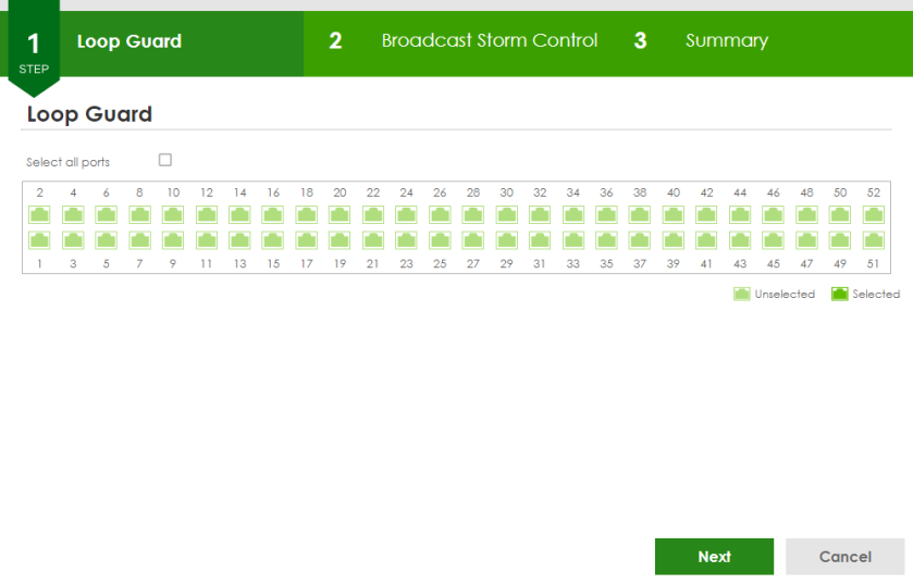
Each field is described in the following table.
Label | Description |
|---|---|
Loop Guard | |
Select all ports | Select all ports to enable the loop guard feature on all ports. You can select a port by clicking it. |
Next | Click Next to show the next screen. |
Cancel | Click Cancel to exit this screen without saving. |
After clicking Next, the Broadcast Storm Control screen appears.
Wizard > Protection > Step 2 Broadcast Storm Control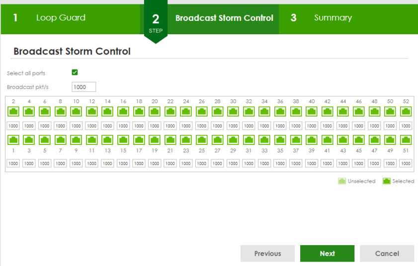
Each field is described in the following table.
Label | Description |
|---|---|
Broadcast Storm Control | |
Select all ports | Select all ports to apply settings on all ports. You can select a port by clicking it. |
Broadcast pkt/s | Specify how many broadcast packets the port receives per second. |
Previous | Click Previous to show the previous screen. |
Next | Click Next to show the next screen. |
Cancel | Click Cancel to exit this screen without saving. |
After clicking Next, the Summary screen appears.
Wizard > Protection > Step 3 Summary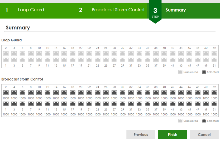
Each field is described in the following table.
Label | Description |
|---|---|
Summary | |
Loop Guard | If the loop guard feature is enabled on a port, the Switch will prevent loops on this port. |
Broadcast Storm Control | If the broadcast storm control feature is enabled on a port, the number of broadcast packets the Switch receives per second will be limited on this port. |
Previous | Click Previous to show the previous screen. |
Finish | Review the information and click Finish to create the task. |
Cancel | Click Cancel to exit this screen without saving. |
VLAN
In VLAN, you can create VLAN, and tag VLAN settings.
Click Wizard > VLAN > VLAN Setting to access this screen.
Wizard > VLAN > VLAN Setting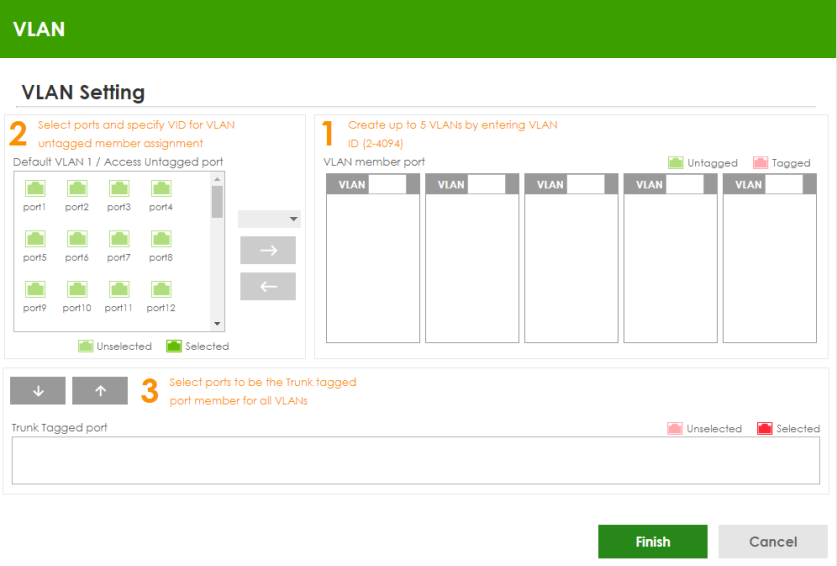
Each field is described in the following table.
Label | Description |
|---|---|
VLAN Setting | |
Default VLAN 1 / Access Untagged port | After you create a VLAN and select the VLAN ID from the drop-down list box, select ports and use the right arrow to add them as the untagged ports to a VLAN group. |
VLAN member port | |
VLAN | Type a number between 2 and 4094 to create a VLAN. |
Trunk Tagged port | Select ports and use the downward arrow to add them as the tagged ports to the VLAN groups you created. |
Finish | Review the information and click Finish to create the task. |
Cancel | Click Cancel to exit this screen without saving. |
QoS
In QoS, you can create QoS settings.
In order to create QoS settings, please do the following. Click Wizard > QoS > QoS Setting to access this screen.
Wizard > QoS > QoS Setting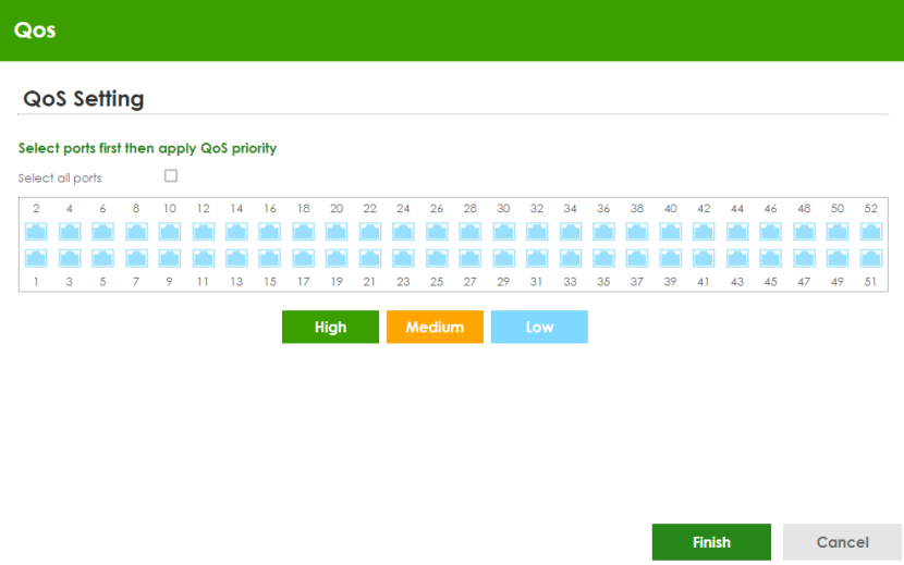
Each field is described in the following table.
Label | Description |
|---|---|
QoS Setting | |
Select all ports | Select all ports to apply settings on all ports. You can select a port by clicking it. |
High | Select ports and click the High button, so they will have high priority. The port’s IEEE 802.1p priority level will be set to 5. Use the PORT > Port Setup screen to adjust the value. |
Medium | Select ports and click the Medium button and, so they will have medium priority. The port’s IEEE 802.1p priority level will be set to 3. Use the PORT > Port Setup screen to adjust the value. |
Low | Select ports and click the Low button, so they will have low priority. The port’s IEEE 802.1p priority level will be set to 1. Use the PORT > Port Setup screen to adjust the value. |
Finish | Review the information and click Finish to create the task. |
Cancel | Click Cancel to exit this screen without saving. |
Web Configurator Layout
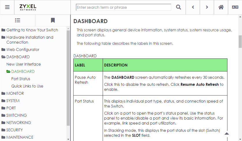
The DASHBOARD screen is the first screen that displays when you access the Web Configurator.
This guide uses the XGS1935-28HP and XGS1935-52HP screens as examples. The screens may vary slightly for different models.
The following figure shows the navigating components of a Web Configurator screen.
Web Configurator Layout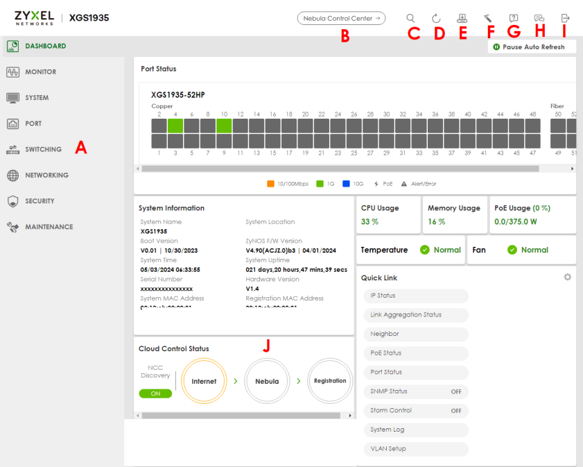
A – Click the menu items to open sub-menu links, and then click on a sub-menu link to open the screen in the main window.
B, C, D, E, F, G, H, I – These are quick links which allow you to perform certain tasks no matter which screen you are currently working in.
B – Click this icon to go to the NCC (Nebula Control Center) portal website.
C – Click this icon to search for specific configurations or status you are looking for. Enter the keywords and click the result link. This will direct you to the specific configuration or status page.
D – Click this icon to update the information in the screen you are currently viewing.
E – Click this icon to save your configuration into the Switch’s non-volatile memory. Non-volatile memory is the configuration of your Switch that stays the same even if the Switch’s power is turned off.
F – Click this icon to display the Setup Wizard that contains the Basic, Protection, VLAN, and QoS setup screens.
G – Click this icon to display web help pages. The help pages provide descriptions for all of the configuration screens.
H – Click this icon to go to the Zyxel Community Biz Forum.
I – Click this icon to log out of the Web Configurator.
J – This displays the Nebula Cloud Control Status. The ON/OFF switch displays if NCC Discovery is enabled. If a status circle turns Orange, it means the Switch is unable to connect to NCC. Hover the mouse over the status circle to check the diagnostic message. You can also click the ON/OFF switch to go to the SYSTEM > Cloud Management screen and check the diagnostic messages. See SYSTEM > Cloud Management for more information.
In the navigation panel, click a main link to reveal a list of sub-menu links.
The following table describes the links in the navigation panel. The navigation panel varies depending on the product model you use.
link | description |
|---|---|
DASHBOARD | This link takes you to the main dashboard screen that displays general system and device information. |
MONITOR | |
ARP Table | This link takes you to a screen that displays the current ARP table of the Switch. You can view the IP and MAC address mapping, VLAN ID, ARP aging time, and ARP entry type of a device attached to a port. |
IP Table | This link takes you to a screen where you can view the IP address and VLAN ID of a device attached to a port. |
IPv6 Neighbor Table | This link takes you to a screen where you can view the Switch’s IPv6 neighbor table. |
MAC Table | This link takes you to a screen where you can view the MAC address and VLAN ID of a device attach to a port. You can also view what kind of MAC address it is. |
Neighbor | This link takes you to a screen where you can view neighbor devices (including non-Zyxel devices) connected to the Switch. |
Path MTU Table | This link takes you to a screen where you can view the IPv6 path MTU information on the Switch. |
Port Status | This link takes you to a screen where you can view the port statistics. |
Routing Table | Click the link to unfold the following sub-link menu. |
IPv4 Routing Table | This link takes you to a screen where you can view the IPv4 routing table for routing information including IP interface and hop count to certain network destinations. |
IPv6 Routing Table | This link takes you to a screen where you can view the IPv6 routing table for routing information including IP interface and hop count to certain network destinations. |
System Information | This link takes you to a screen that displays general system information. |
System Log | This link takes you to a screen where you can view the system log including fail log and system status. |
SYSTEM | |
Cloud Management | This link takes you to a screen where you can enable or disable the Nebula Control Center (NCC) Discovery feature and view the NCC connection status. If Nebula Control Center (NCC) Discovery is enabled, you can have the Switch search for the NCC (Nebula Control Center). The screen also displays a QR code containing the Switch’s serial number and MAC address for handy registration of the Switch at NCC. |
General Setup | This link takes you to a screen where you can configure general identification information about the Switch. |
Hardware Monitor Setup | This link takes you to a screen where you can configure hardware monitor related features such as SFP Detect. |
Interface Setup | This link takes you to a screen where you can configure settings for individual interface type and ID. |
IP Setup | This link takes you to a screen where you can configure the DHCP client, and a static IP address (IP address and subnet mask). |
IPv6 | Click the link to unfold the following sub-link menu. |
IPv6 Status | This link takes you to a screen where you can view the IPv6 table and DNS server. |
IPv6 Global Setup | This link takes you to a screen where you can configure the global IPv6 settings. |
IPv6 Interface Setup | This link takes you to a screen where you can view and configure IPv6 interfaces. |
IPv6 Addressing | This link takes you to a screen where you can view and configure IPv6 link-local and global addresses. |
IPv6 Neighbor Discovery | This link takes you to a screen where you can view and configure neighbor discovery settings on each interface. |
IPv6 Neighbor Setup | configure static IPv6 neighbor entries in the Switch’s IPv6 neighbor table. |
DHCPv6 Client Setup | This link takes you to a screen where you can configure the Switch’s DHCP settings when it is acting as a DHCPv6 client. |
Logins | This link takes you to a screen where you can change the system login password, as well as configure up to four login details. |
SNMP | This link takes you to screens where you can specify the SNMP version and community (password) values, configure where to send SNMP traps from the Switch, enable loopguard/errdisable/poe/linkup/linkdown/lldp/transceiver-ddm/storm-control on the Switch, specify the types of SNMP traps that should be sent to each SNMP manager, and add/edit user information. |
Switch Setup | This link takes you to a screen where you can set up global Switch parameters such as VLAN type. |
Syslog Setup | This link takes you to a screen where you can configure the Switch’s system logging settings and configure a list of external syslog servers. |
Time Range | This link takes you to a screen where you can configure time range for time-oriented features like Classifier. |
PORT | |
Green Ethernet | This link takes you to a screen where you can configure the Switch to reduce port power consumption. |
Link Aggregation | This link takes you to a screen where you can logically aggregate physical links to form one logical, higher-bandwidth link. |
LLDP | Click the link to unfold the following sub-link menu. |
LLDP | This link takes you to screens where you can view LLDP information and configure LLDP and TLV settings. |
LLDP MED | This link takes you to screens where you can configure LLDP-MED parameters. |
PoE Setup | For PoE models. This link takes you to a screen where you can set priorities, PoE power-up settings and schedule so that the Switch is able to reserve and allocate power to certain PDs. |
Port Setup | This link takes you to a screen where you can configure settings for individual Switch ports. |
SWITCHING | |
Layer 2 Protocol Tunneling | This link takes you to a screen where you can configure L2PT (Layer 2 Protocol Tunneling) settings on the Switch. |
Loop Guard | This link takes you to a screen where you can configure protection against network loops that occur on the edge of your network. |
Mirroring | Click the link to unfold the following sub-link menu. |
Mirroring | This link take you to a screen where you can copy traffic from one port or ports to another port in order to examine the traffic from the first port without interference. |
Multicast | Click the link to unfold the following sub-link menu. |
IPv4 Multicast | This link takes you to screen where you can configure various IPv4 multicast features, IGMP snooping, filtering and create multicast VLANs. |
Static Multicast Forwarding By MAC | This link takes you to a screen where you can configure static multicast MAC addresses for port(s). These static multicast MAC addresses do not age out. |
PPPoE Intermediate Agent | This link takes you to screens where you can enable PPPoE (Point-to-Point Protocol over Ethernet) Intermediate Agent and configure per-port, per-port-per-VLAN settings. |
QoS | Click the link to unfold the following sub-link menu. |
Queuing Method | This link takes you to a screen where you can set priorities for the queues of the Switch. This distributes bandwidth across the different traffic queues. |
Priority Queue | This link takes you to a screen where you can set priority tags for different traffic types and specify the priority levels. |
Bandwidth Control | This link takes you to a screen where you can cap the maximum bandwidth allowed on a port. |
Spanning Tree Protocol | Click the link to unfold the following sub-link menu. |
Spanning Tree Protocol Status | This link takes you to a screen where you can view the STP status in the different STP modes (RSTP, MRSTP or MSTP) you can configure on the Switch. |
Spanning Tree Setup | This link takes you to a screen where you can activate one of the STP modes (RSTP, MRSTP or MSTP) on the Switch. |
RSTP | This link takes you to a screen where you can configure the RSTP (Rapid Spanning Tree Protocol) settings on the Switch. |
MSTP | This link takes you to a screen where you can configure the MSTP (Multiple Spanning Tree Protocol) settings on the Switch. |
Static MAC Filtering | This link takes you to a screen to set up static MAC filtering rules. |
Static MAC Forwarding | This link takes you to a screen where you can configure static MAC addresses for a port. These static MAC addresses do not age out. |
VLAN | Click the link to unfold the following sub-link menu. |
VLAN Status | This link takes you to a screen where you can view and search all VLAN groups. |
VLAN Setup | This link takes you to screens where you can: • configure port-based or 802.1Q VLAN. • view detailed port settings and status of the VLAN group. • configure and view 802.1Q VLAN parameters for the Switch. • configure the static VLAN settings on a port. |
Voice VLAN Setup | This link takes you to a screen where you can set up VLANs that allow you to group voice traffic with defined priority and enable the Switch port to carry the voice traffic separately from data traffic to ensure the sound quality does NOT deteriorate. |
Vendor ID Based VLAN Setup | This link takes you to screens where you can set up VLANs that allow you to group untagged packets into logical VLANs based on the source MAC address of the packet. You can specify a mask for the MAC address to create a MAC address filter and enter a weight to set the VLAN rule’s priority. |
NETWORKING | |
ARP Setup | Click the link to unfold the following sub-link menu. |
ARP Learning | This link takes you to a screen where you can configure ARP learning mode on a per-port basis. |
Static ARP | This link takes you to a screen where you can create static ARP entries which do not age out. |
DHCP | Click the link to unfold the following sub-link menu. |
DHCPv4 Relay | This link takes you to screens where you can view DHCPv4 relay status, mode, and configure DHCPv4 relay settings. |
DHCPv6 Relay | This link takes you to a screen where you can enable and configure DHCPv6 relay. |
Static Routing | Click the link to unfold the following sub-link menu. |
IPv4 Static Route | This link takes you to a screen where you can configure IPv4 static routes. A static route defines how the Switch should forward traffic by destination IP address and subnet mask. |
IPv6 Static Route | This link takes you to a screen where you can configure IPv6 static routes. A static route defines how the Switch should forward traffic by destination IP address and prefix length. |
SECURITY | |
AAA | Click the link to unfold the following sub-link menu. |
RADIUS Server Setup | This link takes you to a screen where you can configure your RADIUS (Remote Authentication Dial-In User Service) server settings for authentication. |
AAA Setup | This link takes you to a screen where you can configure authentication, authorization and accounting services through external RADIUS servers. |
Access Control | Click the link to unfold the following sub-link menu. |
Service Access Control | This link takes you to a screen where you can decide what services you may use to access the Switch. |
Remote Management | This link takes you to a screen where you can specify a group of one or more “trusted computers” from which an administrator may use a service to manage the Switch. |
Account Security | This link takes you to a screen where you can configure account security settings on the Switch. |
ACL | Click the link to unfold the following sub-link menu. |
Classifier | This link takes you to screens where you can configure the Switch to group packets based on the specified criteria. |
Policy Rule | This link takes you to a screen where you can configure the Switch to perform special treatment on the grouped packets. |
Storm Control | This link takes you to a screen to set up broadcast filters. |
Errdisable | This link takes you to screens where you can view errdisable status and configure errdisable settings in CPU protection, errdisable detect, and errdisable recovery. |
DHCP Snooping | This link takes you to screens where you can view DHCP snooping database details and configure DHCP snooping settings on ports or VLANs. You can use DHCP snooping to filter unauthorized DHCP packets on the network and to build the binding table dynamically. |
Port Authentication | Click the link to unfold the following sub-link menu. These links take you to screens where you can configure IEEE 802.1x port authentication as well as MAC authentication for clients communicating through the Switch. |
802.1x | The link takes you to a screen where you can activate IEEE 802.1x security on a port. |
MAC Authentication | The link takes you to a screen where you can activate MAC authentication on a port. |
Guest VLAN | The link takes you to a screen where you can activate enable and assign a guest VLAN to a port. |
Port Security | This link takes you to a screen where you can activate MAC address learning and set the maximum number of MAC addresses to learn on a port. |
MAINTENANCE | |
Certificates | The link takes you to a screen where you can import the Switch's CA-signed certificates. |
Cluster Management | This link takes you to a screen where you can configure clustering management and view its status. |
Configuration | Click the link to unfold the following sub-link menu. |
Restore Configuration | This link takes you to a screen where you can upload a stored device configuration file. |
Backup Configuration | This link takes you to a screen where you can save your Switch’s configurations (settings) for later use. |
Erase Running-Configuration | This link takes you to a screen where you can reset the configuration to the Zyxel default configuration settings. |
Save Configuration | This link takes you to a screen where you can save the current configuration (settings) to a specific configuration file on the Switch. |
Configure Clone | This link takes you to a screen where you can copy the basic and advanced settings from a source port to a destination port or ports. |
Diagnostic | This link takes you to a screen where you can ping IP addresses, run traceroute, test ports and show the location of the Switch. |
Firmware Upgrade | This link takes you to a screen to upload firmware to your Switch. |
Reboot System | This link takes you to a screen to reboot the Switch without turning the power off. |
SSH Authorized Keys | This link takes you to a screen where you can authenticate secure SSH connections between a client computer and the Switch (also called the server) without needing a password to connect to the Switch. |
SSH Host Keys | This link takes you to a screen where you can regenerate the Switch's SSH host key. |
Tech-Support | This link takes you to a screen where you can download related log reports for issue analysis. Log reports include CPU history and utilization, crash and memory. |
Tables and Lists
The Web Configurator tables and lists provide several options for how to work with their entries.
Working with Table Entries
Tables have tool icons for working with table entries as shown next. You can select one or more entries, or select the checkbox in the heading row to select all entries. Use the tool icons to modify the selected entries.
Working with a Table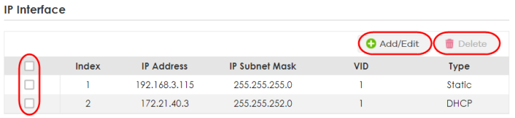
The following table describes the most common table icons.
LABEL | DESCRIPTION |
|---|---|
Select an entry’s checkbox to select a specific entry. Otherwise, select the checkbox in the table heading row to select all entries. | |
Add/Edit | Click this to create a new entry or edit a selected entry. A configuration screen where you can add a new entry or modify the settings of the selected entry will open. In some configuration screens, the Add/Edit button is replaced by the Edit button. This means you can only edit the existing entries in the table. |
Delete | To remove entries, select the entries and click Delete. |
When viewing a list, you can click on an index number to view more details about the entry. If the list has more than one page, click the arrow button to navigate to different pages of entries.
Working on a List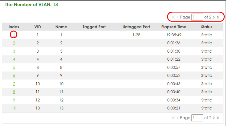
Change Your Password
If you want to change your password, click SYSTEM > Logins to display the screen as shown. See System Login for more information.
Change Administrator Login Password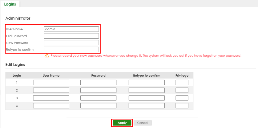
Save Your Configuration
When you are done modifying the settings in a screen, click Apply to save your changes back to the run-time memory. Settings in the run-time memory are lost when the Switch’s power is turned off.
Click the Save link in the upper right of the Web Configurator to save your configuration to non-volatile memory. Non-volatile memory refers to the Switch’s storage that remains even if the Switch’s power is turned off.
Switch Lockout
You could block yourself (and all others) from managing the Switch if you do one of the following:
1 Delete the management VLAN (default is VLAN 1).
2 Delete all port-based VLANs with the CPU port as a member. The “CPU port” is the management port of the Switch.
3 Filter all traffic to the CPU port.
4 Disable all ports.
5 Misconfigure the text configuration file.
6 Forget the password and/or IP address.
7 Prevent all services from accessing the Switch.
8 Change a service port number but forget it.
9 You forgot to log out of the Switch from a computer before logging in again on another computer.
Reset the Switch
If you lock yourself (and others) from the Switch or forget the administrator password, you will need to reload the factory-default configuration file or reset the Switch back to the factory defaults.
Restore Button
Press the RESTORE button for 7 to 10 seconds to have the Switch automatically reboot and restore the factory default file. See LEDs for more information about the LED behavior.
Restore Custom Default (Standalone mode only)
Press the RESTORE button for 3 to 6 seconds to have the Switch automatically reboot and restore the last-saved custom default file. See LEDs for more information about the LED behavior.
Reboot the Switch
Press the RESET button to reboot the Switch without turning the power off. See LEDs for more information about the LED behavior.
Log Out of the Web Configurator
Click Logout in a screen to exit the Web Configurator. You have to log in with your password again after you log out. This is recommended after you finish a management session for security reasons.
Logout button
Help
The Web Configurator’s online help has descriptions of individual screens and some supplementary information.
Click the Help icon on a Web Configurator screen to view an online help description (shown as below) of that screen.
Online Web Help